Hydraulic shovel calibration device and hydraulic shovel calibration method

a technology of hydraulic shovel and calibration device, which is applied in the direction of soil-shifting machines/dredgers, mechanical machines/dredgers, instruments, etc., can solve the problems of difficult to accurately measure the parameters as described, the calibration method is not easy to follow, and the calibration value is not accurate, so as to improve the accuracy of the computation of calibration values, and improve the accuracy of the calibration value computation

Active Publication Date: 2013-06-20
KOMATSU LTD
View PDF6 Cites 31 Cited by
  • Summary
  • Abstract
  • Description
  • Claims
  • Application Information

AI Technical Summary

Benefits of technology

[0017]In the hydraulic shovel calibration device according to the third aspect of the present invention, it is possible to further improve the accuracy of the computation of the calibration values of the parameters based on the working point position information since calibration is performed based on a position of the working point in state where the boom, the arm, or the work tool is extended to the maximum or is contracted to the minimum.
[0018]In the hydraulic shovel calibration device according to the fourth aspect of the present invention, it is possible to further improve the accuracy of the computation of the calibration values of the parameters based on the working point position information since calibration is performed based on the coordinates of the working point at various positions.
[0019]In the hydraulic shovel calibration device according to the fifth aspect of the present invention, it is possible to further improve the accuracy of the computation of the calibration values of the parameters based on the working point position information since calibration is performed based on the coordinates of the working point at various positions.
[0020]In the hydraulic shovel calibration device according to the sixth aspect of the present invention, the swing angles of the boom, the arm, and the work tool are computed from the cylinder stroke. In this case, parameters necessary in the computation of the swing angles are increased while the responsiveness is superior compared to a case where the swing angles are detected using an angle sensor. As a result, ...

Problems solved by technology

However, it is normal that these parameters have errors with regard to design values.
However, it is not easy to accurately measure the parameters as described above using a measurement means such as a measuring tape.
In addition, in a case whe...

Method used


Image

  • Hydraulic shovel calibration device and hydraulic shovel calibration method
  • Hydraulic shovel calibration device and hydraulic shovel calibration method
  • Hydraulic shovel calibration device and hydraulic shovel calibration method

Examples


Embodiment Construction

1. Configuration

1-1. Overall Configuration of Hydraulic Shovel

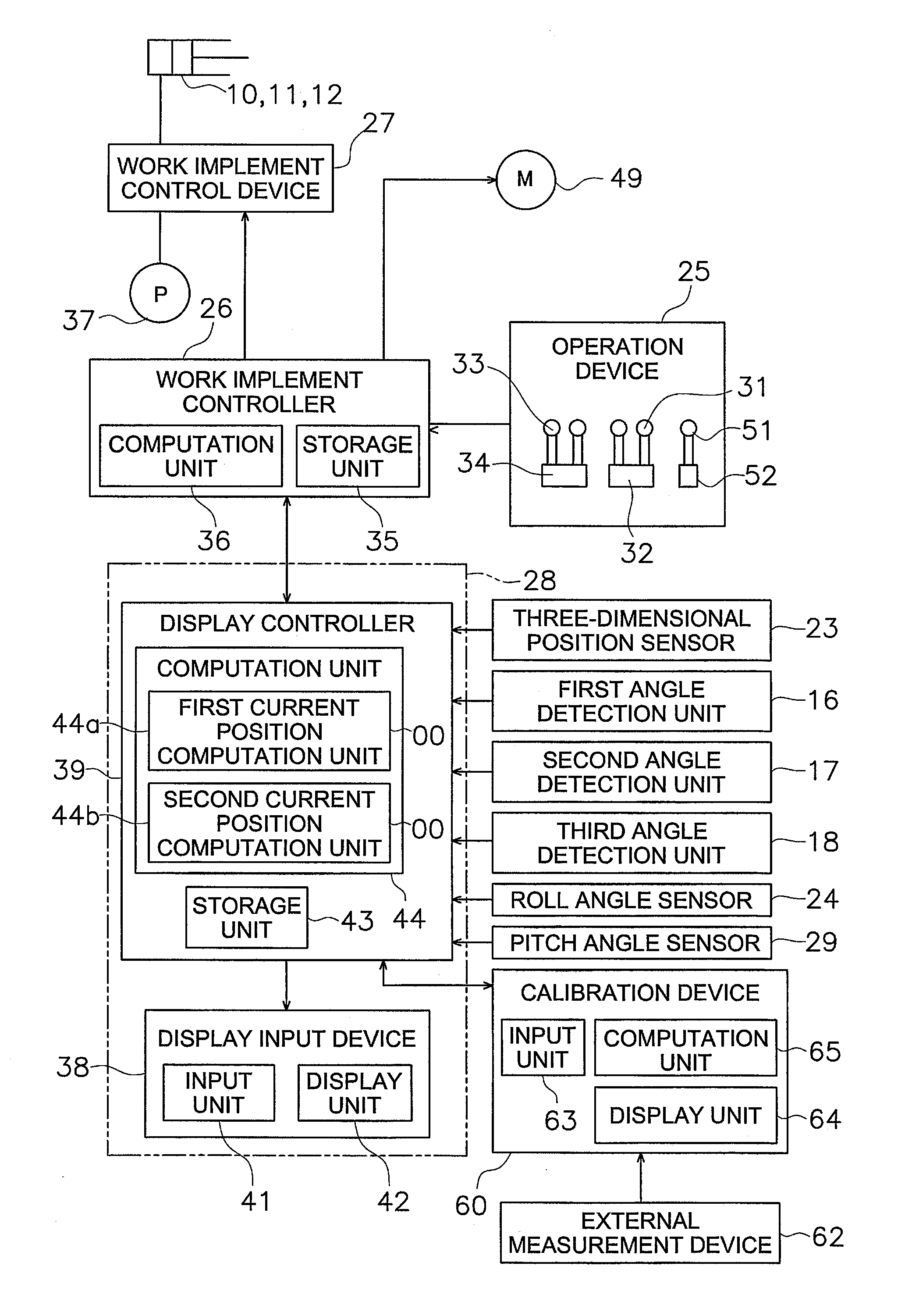
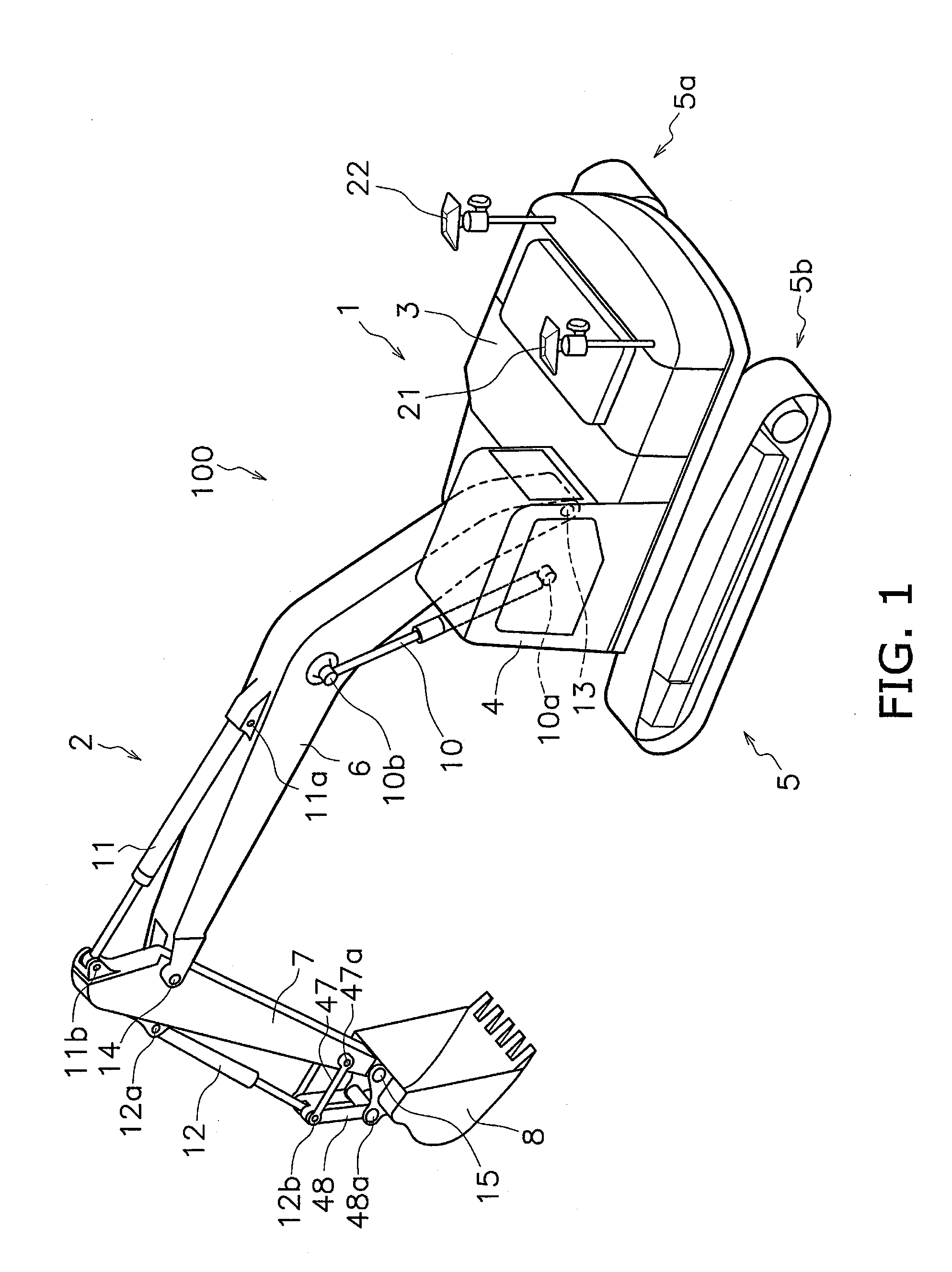
[0046]Below, a calibration device and calibration method for a hydraulic shovel according to a first embodiment of the present invention will be described with reference to the drawings. FIG. 1 is a perspective diagram of a hydraulic shovel 100 which executes calibration using the calibration device. The hydraulic shovel 100 has a vehicle body 1 and a work implement 2. The vehicle body 1 has a pivoting body 3, a cab 4, and a travel unit 5. The pivoting body 3 is pivotally attached to the travel unit 5. The pivoting body 3 includes devices such as a hydraulic pump 37 (refer to FIG. 3), an engine which is not shown, and the like. The cab 4 is placed on a front portion of the pivoting body 3. A display input device 38 and an operation device 25 which will be described later are disposed in the cab 4 (refer to FIG. 3). The travel unit 5 has crawler tracks 5a and 5b and the hydraulic shovel 100 moves due to rotation of the cra...


PUM


Abstract

A hydraulic shovel calibration device is adapted to calibrate parameters in a hydraulic shovel including a current position computation unit configured to compute a current position of a working point included in a work tool of a hydraulic shovel based on a plurality of parameters that indicate dimensions and swing angles of a boom, an arm, and the work tool. The hydraulic shovel calibration device includes an input unit and a calibration computation unit. The input unit is configured and arranged to input working point position information indicating coordinates of a working point included in a work tool of the hydraulic shovel at a pluralty of positions which are measured by an external measurement device. The calibration computation unit is configured to compute calibration values of the parameters based on the working point position information input into the input unit.

Description

CROSS-REFERENCE TO RELATED APPLICATIONS[0001]This application claims priority to Japanese Patent Application No. 2011-065979 filed on Mar. 24, 2011, the disclosure of which is hereby incorporated herein by reference in its entirety.TECHNICAL FIELD[0002]The present invention relates to a hydraulic shovel calibration device and a hydraulic shovel calibration method.BACKGROUND ART[0003]From the past, there is known a hydraulic shovel provided with a position detection device which detects the current position of a working point of a work implement. For example, in the hydraulic shovel disclosed in Japanese Unexamined Patent Application Publication No. 2002-181538, position coordinates of a cutting edge of a bucket are computed based on position information from a GPS antenna. Specifically, position coordinates of the cutting edge of the bucket are computed based on parameters such as a positional relationship of the GPS antenna and a boom pin, lengths of each of a boom, an arm, and the...

Claims


Application Information

Patent Timeline
IPC IPC(8): E02F9/26
CPCE02F9/264G01S19/14G01S19/45G01S19/23E02F3/43E02F9/20G01C15/00
Inventor SEKI, MASANOBU
Owner KOMATSU LTD
Why Eureka
Try Eureka