Control method for laser cladding powder feeding

A control method and laser cladding technology, applied in metal material coating process, coating and other directions, can solve problems such as uneven powder feeding

Active Publication Date: 2021-01-15
宁波中物力拓超微材料有限公司
View PDF13 Cites 1 Cited by
  • Summary
  • Abstract
  • Description
  • Claims
  • Application Information

AI Technical Summary

Problems solved by technology

[0004] Therefore, the embodiment of the present invention provides a control method for laser cladding powder feeding, and the present invention can effectively solve the technical problem of uneven powder feeding, Achieved the technical effect of stable powder feeding and uniform powder feeding

Method used


Image

  • Control method for laser cladding powder feeding
  • Control method for laser cladding powder feeding
  • Control method for laser cladding powder feeding

Examples


no. 1 example

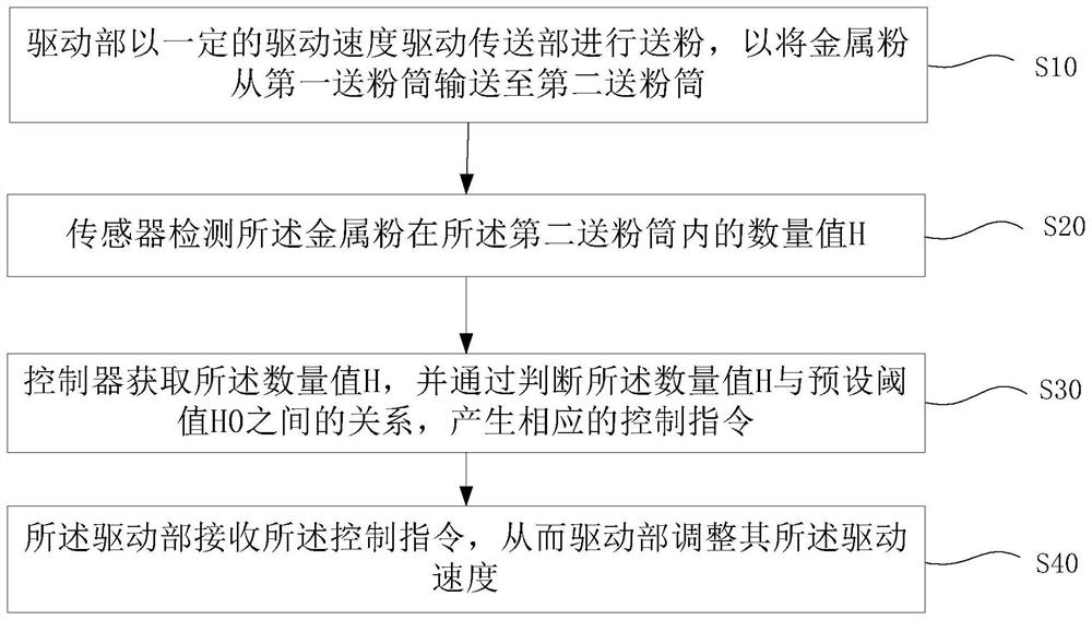
[0045] see figure 1 , the embodiment of the present invention provides a control method for laser cladding powder feeding, including:

[0046] S10: the driving part 240 drives the conveying part 140 at a certain driving speed to perform powder pollination, so as to transport the metal powder from the first powder feeding cylinder 110 to the second powder feeding cylinder 170;

[0047] S20: The sensor detects the quantity value H of the metal powder in the second powder feeding cylinder 170;

[0048] S30: The controller obtains the quantity value H, and generates a corresponding pollination control command by judging the relationship between the quantity value H and the preset threshold value H0;

[0049] S40: The driving unit 240 receives the pollination control command, so that the driving unit 240 adjusts its driving speed.

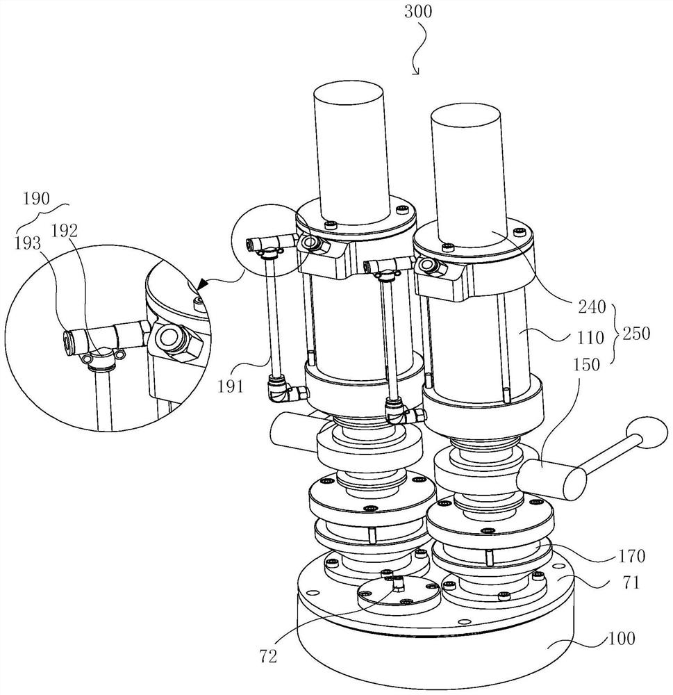
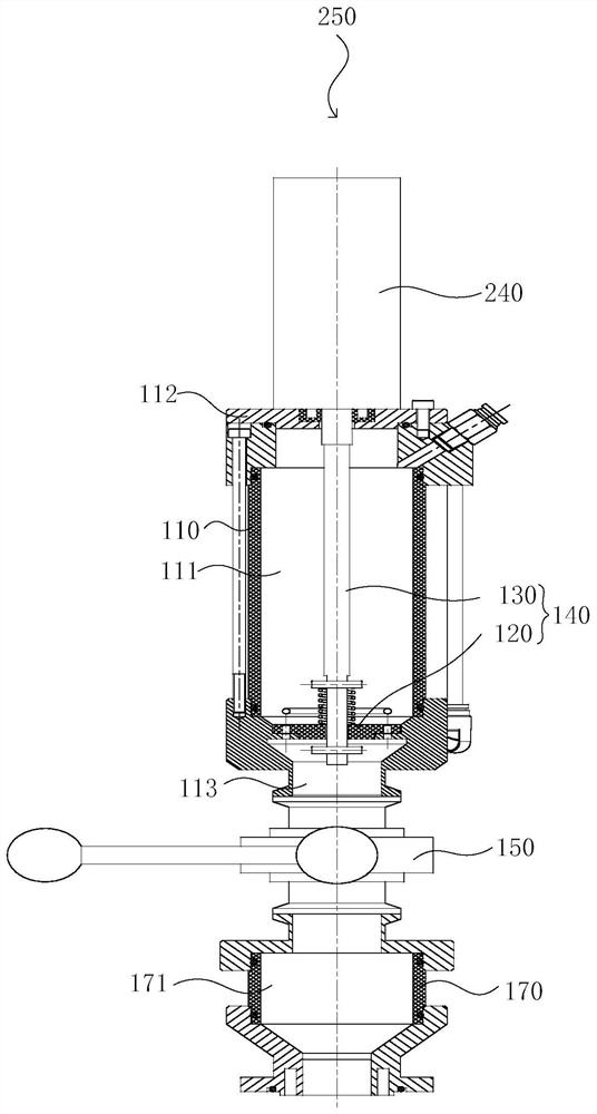
[0050] preferred, see figure 2 , the embodiment of the present invention provides a powder feeding device 300, including: at least two powder feedi...

no. 2 example

[0069] see Figure 8 In the second embodiment provided by the present invention, steps S31 and S41 are performed on the basis of the above-mentioned first embodiment S20.

[0070] Preferably, S31 is executed, the sensor transmits the quantity value H of metal powder detected in the second powder storage space to the controller, and the controller judges the quantity value H, if the controller judges that the quantity value H is less than The minimum threshold HO of the set normal threshold interval 小 , an accelerated pollination control instruction will be generated.

[0071] Further, step S41 is executed, the controller issues the accelerated pollination control instruction to the driving unit 240, and the driving unit 240 drives the transmission unit 140 to perform powder feeding according to the accelerated pollination control instruction at a speed greater than the driving speed in S10 .

[0072] Wherein, when steps S31 and S41 are executed, the control valve 150 is in ...

no. 3 example

[0074] see Figure 9 In the third embodiment provided by the present invention, steps S32 and S42 are performed on the basis of the above-mentioned first embodiment S20.

[0075] Preferably, S32 is executed, the sensor transmits the quantity value H of metal powder detected in the second powder storage space to the controller, and the controller judges the quantity value H, if the quantity value H is greater than the set value at this time Set the maximum value of the threshold HO 大 When , it will generate slow down or suspend pollination control instructions.

[0076] Further, step S42 is executed again. If it is a pollination suspension control instruction, the controller transmits the deceleration pollination control instruction to the drive part 240, and the drive part 240 uses the deceleration pollination control instruction to be smaller than the one in S10. The driving speed drives the conveying unit 140 to pollinate; if it is a pollination suspension control instruct...


PUM


Abstract

The invention discloses a control method for laser cladding powder feeding. The control method for laser cladding powder feeding comprises the steps that S10, a driving part drives a conveying part tofeed powder at a certain driving speed, so that metal powder is conveyed to a second powder feeding barrel from a first powder feeding barrel; S20, a sensor detects a quantity value H of the metal powder in the second powder feeding barrel; S30, a controller obtains the quantity value H and generates a corresponding powder conveying control instruction by judging the relation between the quantityvalue H and a preset threshold value H0; and S40, the driving part receives the powder conveying control instruction, so that the driving part adjusts the driving speed. The technical problem of uneven powder feeding can be effectively solved, and the technical effects of stable powder conveying and even powder feeding are achieved.

Description

technical field [0001] The invention is applicable to the technical field of laser cladding, and in particular relates to a control method for laser cladding powder feeding. Background technique [0002] At present, in the processing technology fields such as laser cladding and surface spraying, a large number of powder feeding devices are needed to transport metal powder to designated areas for laser cladding or surface spraying operations. [0003] Most of the existing technologies use negative pressure devices to transport metal powder, but the change of powder volume in the powder cylinder will have a great impact on the actual powder delivery volume, thus affecting the cladding effect; the structure of the powder adding device is also relatively simple, In the powder feeding process, the powder feeding rate cannot be effectively controlled, and the change of powder demand cannot be met, resulting in a large difference in the bulk density of the powder in the original po...

Claims


Application Information

Patent Timeline
Patent Type & Authority Applications(China)
IPC IPC(8): C23C24/10
CPCC23C24/103Y02P10/25
Inventor 唐建宁王奕刘代刚
Owner 宁波中物力拓超微材料有限公司
Why Eureka
Try Eureka