Deep Foundation Pit Large Slope Upside-Down Steel Bolt-spray Support Structure and Its Construction Method

A technology of bolting and shotcrete support and construction method, which is applied in basic structure engineering, excavation, construction, etc., can solve the problems of inconspicuous distinction of key areas, increased construction cost and construction period, etc., and is conducive to soil unloading and foundation pit safety. Reliable and effective in improving construction efficiency

Active Publication Date: 2022-06-28
CHINA CONSTR EIGHT ENG DIV CORP LTD
View PDF8 Cites 0 Cited by
  • Summary
  • Abstract
  • Description
  • Claims
  • Application Information

AI Technical Summary

Problems solved by technology

There are various types of foundation pit support. Currently, it is used for the protruding part of the external corner in the support plane of the foundation pit, and the post-excavation part of the back support, such as the hanging-type civil air defense access stairs and air shafts protruding from the main underground structure. For this kind of protruding For the suspended civil air defense stairs and air shafts and other parts of the main outline of the main underground structure, the traditional support method usually arranges the support piles along the reserved structural construction work surface along the outer outline of the underground structure. The support standard of this method is uniform, and the secondary, The key areas are not clearly distinguished, and the excavation can only be done after setting up the support, which will easily lead to an increase in the amount, construction cost and construction period of earthwork excavation, foundation pit support, earthwork backfill, etc.

Method used


Image

  • Deep Foundation Pit Large Slope Upside-Down Steel Bolt-spray Support Structure and Its Construction Method
  • Deep Foundation Pit Large Slope Upside-Down Steel Bolt-spray Support Structure and Its Construction Method
  • Deep Foundation Pit Large Slope Upside-Down Steel Bolt-spray Support Structure and Its Construction Method

Examples


Embodiment Construction

[0048] The embodiments of the present invention are described below through specific specific examples, and those skilled in the art can easily understand other advantages and effects of the present invention from the contents disclosed in this specification. The present invention can also be implemented or applied through other different specific embodiments, and various details in this specification can also be modified or changed based on different viewpoints and applications without departing from the spirit of the present invention.

[0049] The present invention will be further described in detail below with reference to the accompanying drawings and specific embodiments.

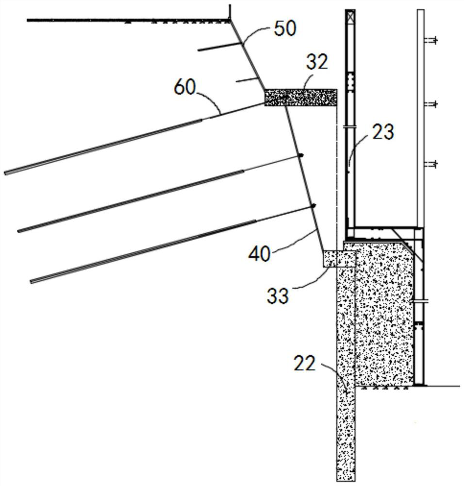
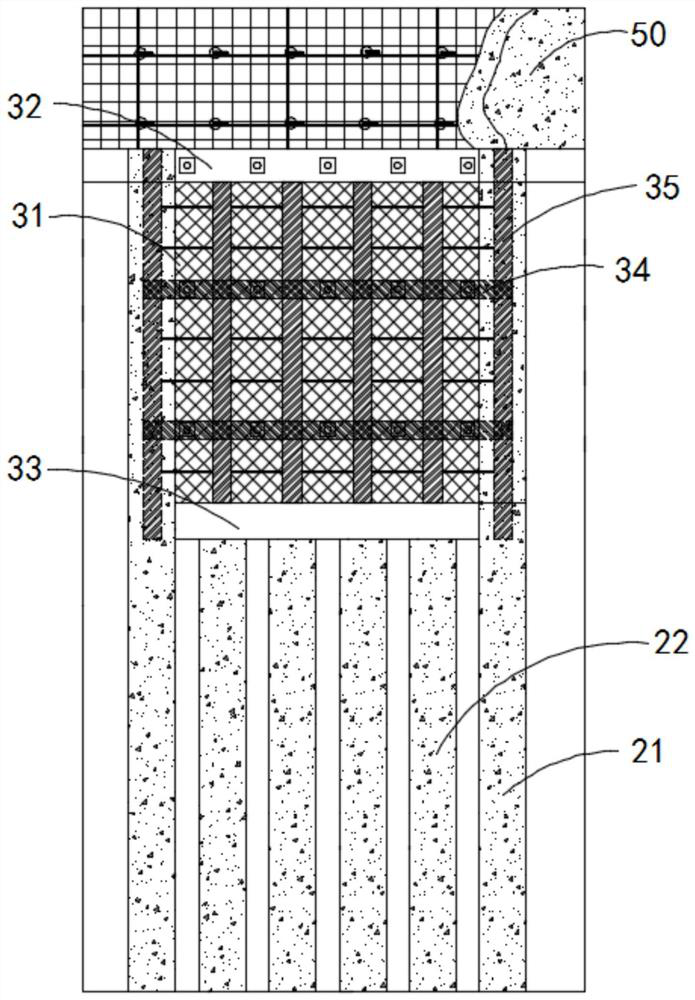
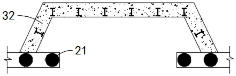
[0050] The invention provides a construction method for a large-slope upside-down type steel bolt-and-shot support structure in a deep foundation pit. The basement in the foundation pit is excavated and supported at the position to be extended, and the construction method includes the following steps: ...


PUM


Abstract

The invention discloses a large-slope upside-down steel anchor-spray support structure for a deep foundation pit, which supports the support pit formed by excavating the basement in the foundation pit at a position to be protruded. The support structure includes: A first support pile and a second support pile, the second support pile is correspondingly arranged at a corresponding position of the support pit and the elevation of the second support pile is lower than the first support pile; The crown beam on the top of the first support pile; the upper support beam on the inner wall of the support pit, the upper support beam is supported on the inner wall of the support pit and the upper support The end of the beam protrudes from the support pit and is fixedly connected to the crown beam on the first support pile; the protective plate is arranged at the bottom of the upper support beam and is attached to the inner wall of the support pit ; the lower support beam on the second support pile, the lower support beam is provided with a certain distance from the inner wall of the support pit, and the lower support beam and the upper support beam pass through The protective plate is fixedly connected.

Description

technical field [0001] The invention relates to the technical field of building construction, in particular to a large-slope upside-down type steel bolt and shotcrete support structure for a deep foundation pit and a construction method thereof. Background technique [0002] Foundation pit support is an essential process in the construction process. There are many kinds of foundation pit support methods. Currently, it is used for the protruding parts of the outer corner and the back excavation parts in the support plane of the foundation pit, such as the suspended civil air defense access stairs, air shafts, etc., which protrude from the main underground structure. For parts such as suspended civil air defense stairs and air shafts on the main outline of the underground main structure, the traditional supporting form usually arranges the supporting piles along the structural construction work surface reserved for the outer outline of the underground structure. The key areas...

Claims


Application Information

Patent Timeline
Patent Type & Authority Patents(China)
IPC IPC(8): E02D17/04E02D5/76
CPCE02D17/04E02D5/76E02D2300/0029E02D2600/30E02D2250/0046
Inventor 丁鲁波丛利吉柳彧赵文杰高健赵春阳孙庆鑫冯天龙张元会
Owner CHINA CONSTR EIGHT ENG DIV CORP LTD
Why Eureka
Try Eureka