

Brake cylinder arrangement and braking system
A technology for brake cylinders and motor vehicles, which is applied to braking action starting devices, hydraulic brake transmission devices, brakes, etc., can solve complex cost and other problems, and achieve the effect of favorable operation.
- Summary
- Abstract
- Description
- Claims
- Application Information
AI Technical Summary
Problems solved by technology
Method used
Image

Examples
Embodiment Construction
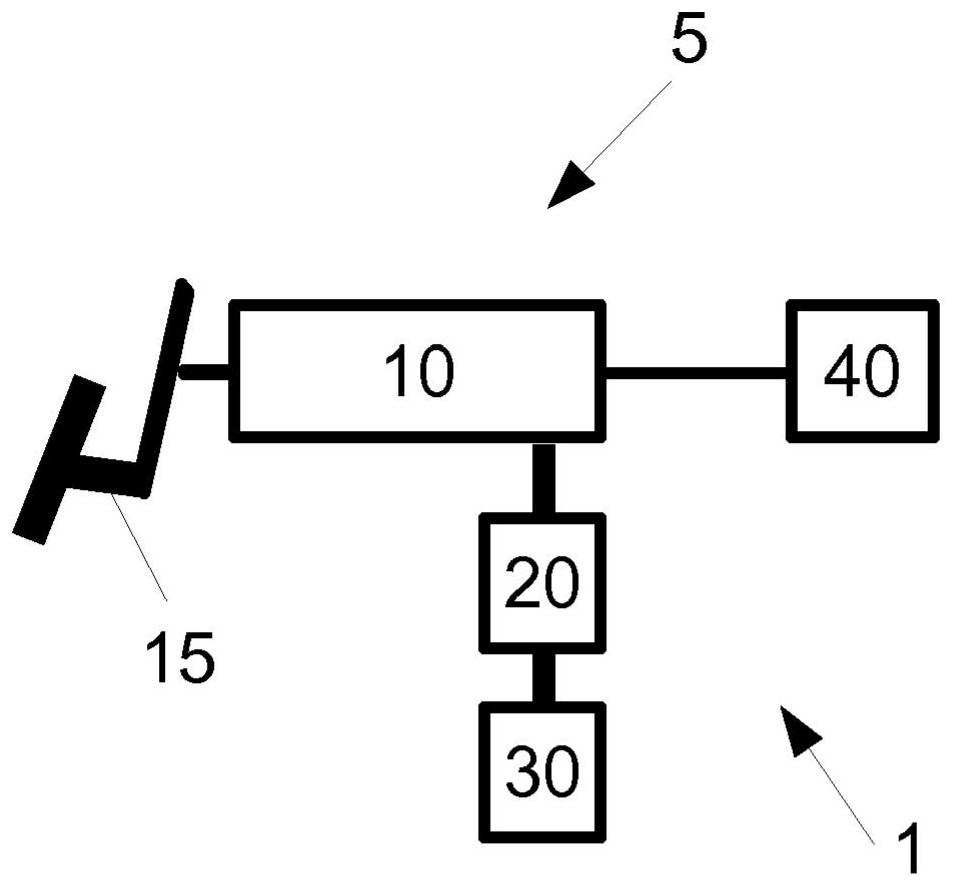
[0022] figure 1 A braking system 1 according to an exemplary embodiment of the invention is shown. The brake system 1 includes a brake cylinder device 5 , a brake pedal 15 and a plurality of brakes 40 . It should be understood that these components are only schematically shown in the block diagrams herein.
[0023] The brake cylinder arrangement 5 has a brake cylinder 10 which is connected to a brake pedal 15 . The driver can thus generate pressure in brake cylinder 10 by actuating brake pedal 15 . The brake 40 can thus be actuated.
[0024] Brake cylinder arrangement 5 also has a pressure reducer 20 and a pressure sensor 30 . As shown, a pressure sensor 30 is connected to the brake cylinder 10 via a pressure reducer 20 .
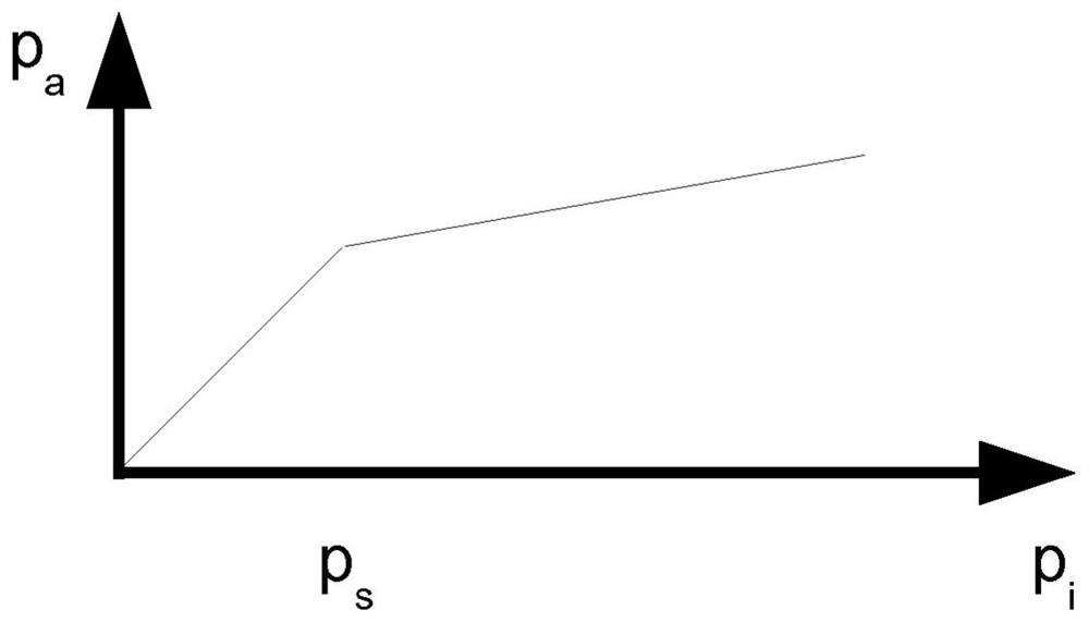
[0025] The pressure reducer 20 has the figure 2 The transfer characteristic curves shown in . Here, the input pressure p is shown on the horizontal axis i , on the vertical axis shows the output pressure p a .
[0026] Therefore, the input pressu...
PUM
 Abstract
Description
Claims
Application Information