
A cooling motor
A motor body and arc-shaped technology, which is applied in the field of heat dissipation motors, can solve the problems of large motor damage, large motor vibration, and low heat dissipation efficiency, and achieve energy saving, small vibration damage, and safe and reliable use.
- Summary
- Abstract
- Description
- Claims
- Application Information
AI Technical Summary
Problems solved by technology
Method used
Image

Examples
Embodiment 1
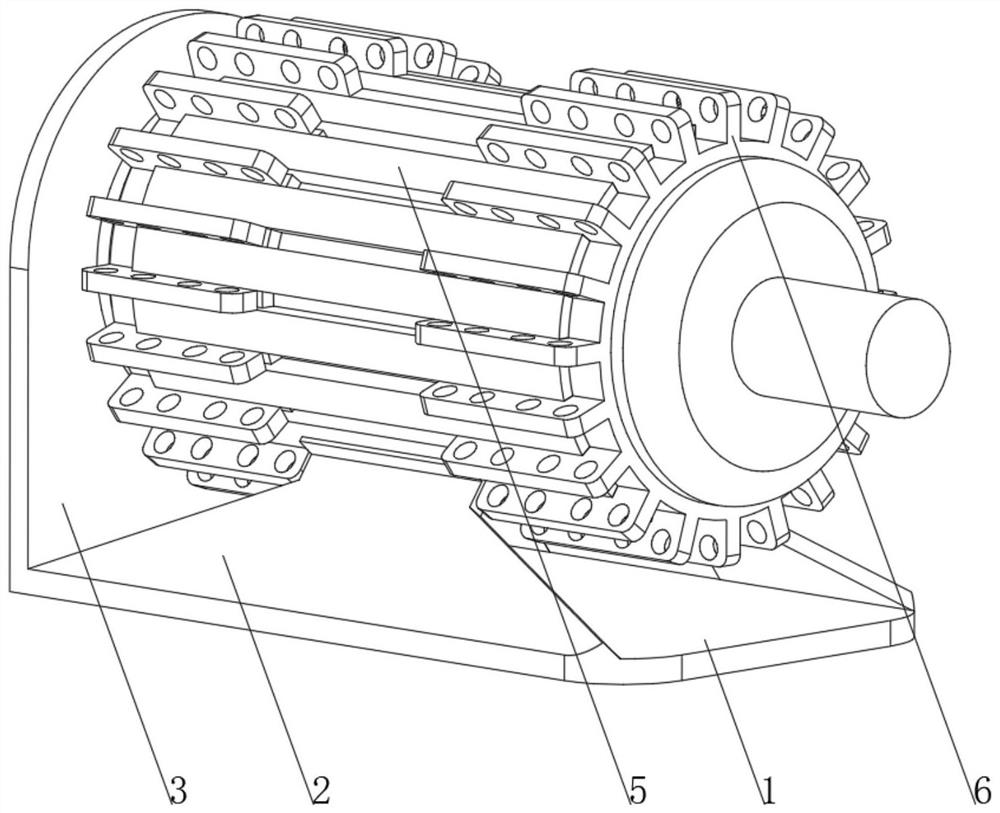
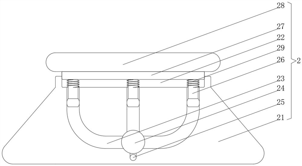
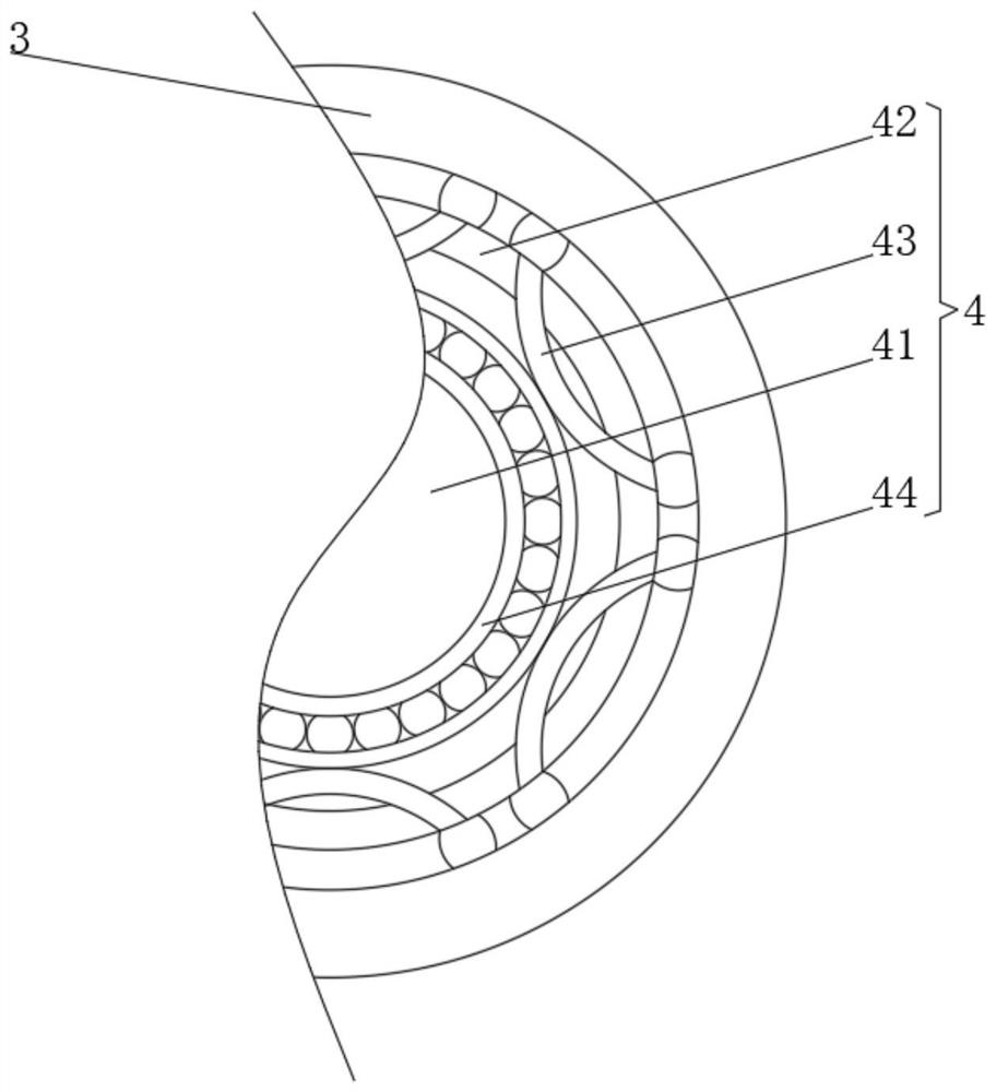
[0034] see Figure 1-3, the present invention provides a technical solution: a heat dissipation motor, including a base 1, a buffer device 2 is fixedly connected to both sides of the top of the base 1, a positioning plate 3 is fixedly connected to one end of the base 1, and the center position of one side of the positioning plate 3 is set There is a positioning device 4, the top of the buffer device 3 is fixedly connected to the motor body 5, and one end of the motor body 5 is provided with a cooling device 6, the buffer device 2 includes a support plate 21, the top of the support plate 21 is provided with a buffer groove 22, and the bottom of the inner wall of the buffer groove 22 is opened There is an air passage 23, the end of the air passage 23 away from the buffer tank 22 is connected with an air chamber 24, the bottom of the air chamber 24 is connected with an air outlet 25, the inner wall of the air passage 23 is slidingly connected with a piston rod 26, and one end of t...
Embodiment 2
[0037] see Figure 1-5 , on the basis of Embodiment 1, the present invention provides a technical solution: the cooling device 6 includes a control cavity 61, the center of the inner wall of the control cavity 61 is fixedly connected with a control seat 62, and the top of the control seat 62 is provided with a vibration groove 63. The bottom of the slot 63 is rotatably connected with a spring piece 64, and the top of the spring piece 64 is rotatably connected with a push rod 65. The top side of the push rod 65 is provided with an arc-shaped slide hole 66, and the inner wall of the arc-shaped slide hole 66 is slidably connected with a slide bar 67. One end is fixedly connected with an arc-shaped pressing rod 68, and the central position of the arc-shaped pressing rod 68 is rotationally connected with the inner wall of the control cavity 61 through a rotating bolt 69. The end of the arc-shaped pressing rod 68 away from the slide bar 67 is fixedly connected with a pressure head 61...
PUM
 Abstract
Description
Claims
Application Information