An intelligent petrochemical fire extinguishing equipment system

A technology of petrochemical and fire extinguishing equipment, applied in fire rescue, etc., can solve the problems of injury, fireman's physical exertion, easy to knock down, etc., and achieve the effects of reducing impact, convenient observation of fire, and reducing physical consumption

Active Publication Date: 2022-02-25
山东胜星仓储有限公司
View PDF0 Cites 0 Cited by
  • Summary
  • Abstract
  • Description
  • Claims
  • Application Information

AI Technical Summary

Problems solved by technology

[0004] The purpose of the present invention is to provide an intelligent petrochemical fire-fighting equipment system to solve the problems of high physical exertion of firefighters, easy to cause injury and easy to overthrow proposed in the background technology

Method used


Image

  • An intelligent petrochemical fire extinguishing equipment system
  • An intelligent petrochemical fire extinguishing equipment system
  • An intelligent petrochemical fire extinguishing equipment system

Examples


Embodiment 1

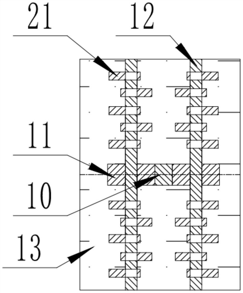
[0041] Such as image 3 As shown, a plurality of cams 21 are respectively fixedly arranged on the four rotating shafts 12, and the gear rack 10 meshes with the gear 11 to drive the rotating shaft 12 to rotate, thereby driving the plurality of cams 21 on the rotating shaft 12 to rotate. Since the left and right sides of the rack 10 The rotation direction of the gear 11 is opposite, and the cams 21 on the left and right sides of the rack 10 all support the buffer body inside the buffer structure 14 in opposite directions.

Embodiment 2

[0043] Such as Figure 6 , 7 As shown, on the basis of Embodiment 1, the non-Newtonian fluid material 13 in the buffer structure 14 is replaced by a rubber material 22. At this time, the structure in the buffer structure 14 is set as Figure 6 As shown, the cam 21 is arranged on the housing 27. When the cam 21 rotates, the front end of the cam 21 contacts with the rubber material 22 and generates friction to buffer the external force.

Embodiment 3

[0045] Such as Figure 4 , 5 As shown, a toggle shaft 25 is fixedly connected to one side of the cam 21, and a toggle groove 26 matched with the toggle shaft 25 on the adjacent cam 21 is provided on the other side of the cam 21, and the two sides of the gear 11 are similar. The two cams 21 on both sides of the gear 11 are fixedly connected to the rotating shaft 12, and the remaining cams 21 on both sides of the gear 11 are flexibly connected to the rotating shaft 12, and each cam 21 is staggered by a certain angle around the rotating shaft 12. On the first layer of cams 21 on both sides of the gear 11 The toggle shaft 25 is correspondingly inserted into the toggle groove 26 on the second layer of cam 21, and so on, as Figure 4 , 5 As shown, when the rotating shaft 12 rotates clockwise, it drives the first layer of cams 21 on both sides of the gear 11 to rotate, and when the cam 21 rotates to a certain angle, the toggle shaft 25 rotates to the toggle groove 26 on the second ...


PUM


Abstract

The invention discloses an intelligent petrochemical fire extinguishing equipment system, comprising a first fixing plate and a motor, wherein the motor is fixedly installed on the lower surface of the left end of the first fixing plate. In the closed space enclosed by the second fixed plate, the third fixed plate and the two protective plates, the fire water gun can be stored and supported to reduce the physical consumption of firefighters due to long-term spraying. By setting protective plates on both sides of the fire water gun, the transmission During the upward movement of the board, it can drive the two protective boards on both sides to move upward synchronously. The protective board can be made of transparent fireproof and high temperature resistant material, which can be used as a protective shield to shield and protect firefighters, and is convenient for fire fighting. Personnel observe the fire situation, and by setting a buffer structure at the bottom of the shock-absorbing plate, the buffer structure buffers the reaction force of the fire water gun, which greatly reduces the impact on the firefighters and effectively protects the personal safety of the firefighters.

Description

technical field [0001] The invention belongs to the related technical field of fire fighting, and in particular relates to an intelligent petrochemical fire fighting equipment system. Background technique [0002] The petrochemical industry provides support and services for agriculture, energy, transportation, machinery, electronics, textiles, light industry, construction, building materials and people's daily life, and occupies a pivotal position in the national economy. Therefore, the petrochemical industry's fire protection Homework is especially important. [0003] The existing petrochemical fire-fighting equipment system technology has the following problems: in the process of using the fire-fighting water gun to extinguish the fire, the fire-fighting personnel are required to support the water-cannon, and the physical strength of the fire-fighting personnel is greatly consumed under long-term spraying. , The explosion and falling objects accompanying the fire scene wi...

Claims


Application Information

Patent Timeline
Patent Type & Authority Patents(China)
IPC IPC(8): A62C3/06A62C31/02A62C31/28
CPCA62C3/06A62C31/02A62C31/28
Inventor 李农李金华徐兴海李海峰李国旗杜忠伟
Owner 山东胜星仓储有限公司
Why Eureka
Try Eureka