Numerical control large-diameter deep hole semi-fine boring head device

A semi-finish boring and large-diameter technology, which is applied in the direction of boring head, turning equipment, tool holder accessories, etc., can solve the problems of workpiece size change, inconsistent inner hole size inlet and outlet, and old structure of large hole boring tools, etc., to achieve The effect of stable processing size, lower skill requirements and saving consumables

Inactive Publication Date: 2021-08-24
SHANDONG HUAYU UNIV OF TECH
View PDF13 Cites 2 Cited by
  • Summary
  • Abstract
  • Description
  • Claims
  • Application Information

AI Technical Summary

Problems solved by technology

[0002] At present, the existing technology is a deep hole machine tool. In order to process deep hole processing with an inner hole size of φ800 ~ φ1900mm, the processing length of the workpiece can reach 16 meters. The existing large hole boring tool structure cannot meet the processing requirements, and a set of special CNC is required. Large diameter deep hole semi-fine boring head device
[0003] The existing large hole boring tool structure is relatively old, such as figure 1 As shown, the boring tool body 1 is installed on the deep hole processing machine tool through threads, and the support bar is installed in the support groove. During the processing, the wear of the blade will reduce the processing size of the inner hole, resulting in the change of the workpiece size, which cannot reach the user. requirements, it is impossible to compensate for the wear of the support bar, so that the inner hole size is inconsistent with the inlet and outlet

Method used


Image

  • Numerical control large-diameter deep hole semi-fine boring head device
  • Numerical control large-diameter deep hole semi-fine boring head device
  • Numerical control large-diameter deep hole semi-fine boring head device

Examples


Embodiment Construction

[0032] Other objects and advantages of the present invention will become clear by explaining the following preferred embodiments of the present invention.

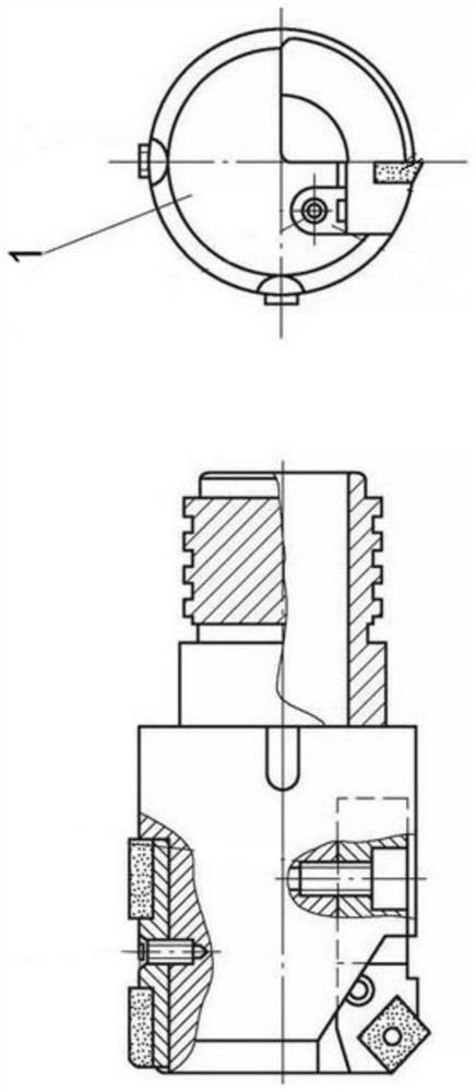
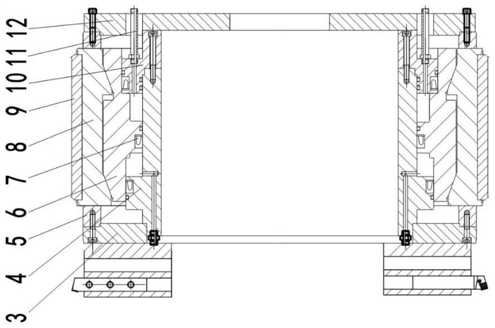
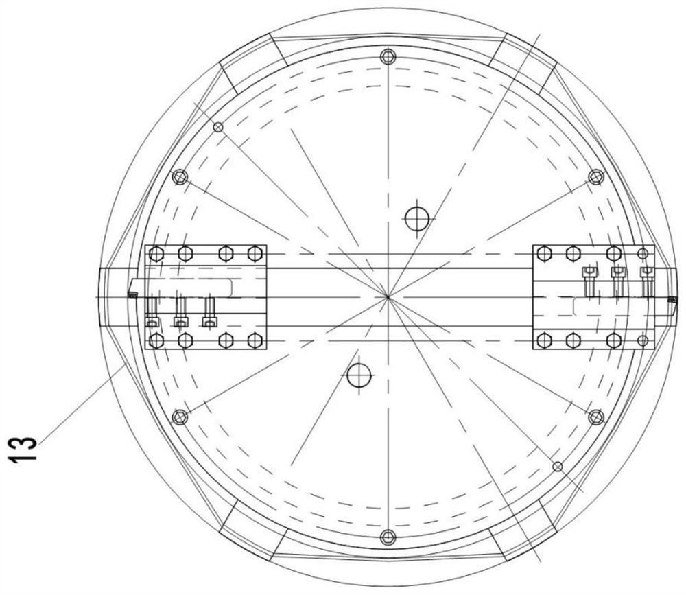
[0033] Figure 1-Figure 13 It shows a structural schematic diagram of a CNC large-diameter deep-hole semi-finishing head device proposed by the present invention. For the convenience of description, the "up", "down", "left" and "right" referred to below are consistent with the up, down, left and right directions of the drawings themselves, but do not limit the structure of the present invention.

[0034] Such as Figure 1-Figure 13 As shown, a CNC large-diameter deep-hole semi-finishing boring head device includes a boring head body 5, a cutter body 17, a support bar compensation structure and a cutter body compensation structure, wherein: the support bar compensation structure includes a fixed piston 4, a drive member and The moving body 8, the fixed piston 4 is fixedly connected to the boring head body 5, the driving p...


PUM


Abstract

The invention relates to the technical field of deep hole machine tools, in particular to a numerical control large-diameter deep hole semi-fine boring head device. The semi-fine boring head device comprises a boring head body, a cutter body, a supporting strip compensation structure and a cutter body compensation structure, wherein the supporting strip compensation structure comprises a fixed piston, a driving part and a moving body, the fixed piston is fixed to the boring head body, the driving part can move in the axial direction of the boring head body, a supporting strip is installed on the moving body, and the moving body is movably supported on the boring head body; the driving part and the moving body are provided with conical surfaces which are matched with each other; and the cutter body compensation structure comprises a driving mechanism and a taper mandrel, a conical surface is arranged at one end of the taper mandrel, the cutter body can abut against the conical surface, and the taper mandrel axially moves to push the cutter body to move in the radial direction of the boring head body. According to the embodiment , the supporting strip and the cutter body can compensate the abrasion loss in the radial size, the consistency of front and back machining sizes of a workpiece is ensured, consumables for replacing the supporting strips are omitted, the machining size is stable, and deep hole machining of the inner hole size of phi 800-phi 1900 mm is smoothly carried out.

Description

technical field [0001] The invention relates to the technical field of deep-hole machine tools, in particular to a numerically controlled large-diameter deep-hole semi-finish boring head device. Background technique [0002] At present, the existing technology is a deep hole machine tool. In order to process deep hole processing with an inner hole size of φ800 ~ φ1900mm, the processing length of the workpiece can reach 16 meters. The existing large hole boring tool structure cannot meet the processing requirements, and a set of special CNC is required. Large diameter deep hole semi-finishing boring head device. [0003] The existing large hole boring tool structure is relatively old, such as figure 1 As shown, the boring tool body 1 is installed on the deep hole processing machine tool through threads, and the support bar is installed in the support groove. During the processing, the wear of the blade will reduce the processing size of the inner hole, resulting in the chang...

Claims


Application Information

Patent Timeline
Patent Type & Authority Applications(China)
IPC IPC(8): B23B27/00B23B29/034
CPCB23B27/00B23B29/03446
Inventor 谭德宁张书华王学军
Owner SHANDONG HUAYU UNIV OF TECH
Why Eureka
Try Eureka