A cutting force measuring device

A measuring device and cutting force technology, applied in the direction of measuring/indicating equipment, metal processing equipment, metal processing machinery parts, etc., can solve the problems of unsuitable real-time online monitoring, inconvenient wire power supply, and restrictions on popularization and application, and achieve integration and High reliability, no obvious resonance, and simple overall structure

Active Publication Date: 2022-05-06
ZHEJIANG NORMAL UNIVERSITY
View PDF0 Cites 0 Cited by
  • Summary
  • Abstract
  • Description
  • Claims
  • Application Information

AI Technical Summary

Problems solved by technology

However, since the drill bit is mostly in a rotating state during processing, the power supply problem of the monitoring system has not been well resolved: the wire power supply is inconvenient and unsafe, and the battery power supply needs to be replaced frequently. The force of machining the workpiece reverses the cutting force on the drill bit. This kind of measurement error is large and is not suitable for real-time online monitoring in the production process, which seriously restricts the popularization and application of online monitoring technology of cutting force in drilling.

Method used


Image

  • A cutting force measuring device
  • A cutting force measuring device
  • A cutting force measuring device

Examples


Embodiment Construction

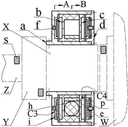
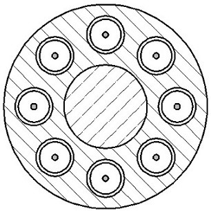
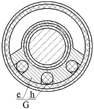
[0032]The present invention proposes a cutting force measuring device, the device is installed on the spindle X of the drilling machine through screws, the end of the spindle X is equipped with a drill bit Z through the fixture Y, and the cutting force measuring device is located between the bed W and the fixture Y; the proposed The cutting force measuring device is mainly composed of casing a, ring frame b, ring plate c, ring cover d, exciter G, limit block f, sensor s, circuit board p and transducer i, casing a, ring The frame b, the ring plate c and the ring cover d are all ring structures; the exciter G is a rolling body h, or is composed of a rolling body h and an inertial body e, and the material of the rolling body h is a magnetic material; the transducer i is composed of a coupling plate i1 and piezoelectric film i2 are bonded, the coupling film i1 is ring-shaped, and the piezoelectric film i2 is circular; the sensor s is installed on the drill bit Z, the fixture Y or t...


PUM


Abstract

The invention relates to a cutting force measuring device, which belongs to the technical field of new energy and cutting force monitoring. It consists of a casing, a ring frame, a ring plate, a ring cover, an exciter, a limit block, a sensor, a circuit board and a transducer. The rolling body of the exciter is a magnetic ball or a magnetic column; It is formed by bonding electric sheets; the sensor is installed on the drill bit, fixture or spindle, the circuit board is installed on the ring cover; the casing is installed on the spindle, the ring cover is installed at the end of the outer ring groove of the casing, and the convex ring of the ring cover Placed in the outer ring groove, the transducer, ring frame, ring plate and transducer are sequentially crimped between the convex ring and the bottom wall of the outer ring groove; the exciter is installed in the inner ring groove of the ring frame, and the transducer The material of the coupling plate is ferromagnetic material; when the main shaft rotates, the transducer and the exciter rotate relative to each other, and the exciter forces the transducer to produce reciprocating axial bending deformation and converts mechanical energy into electrical energy. The electrical energy is supplied to the sensor after being processed by the conversion circuit. The relevant cutting force parameters are obtained in real time and then transmitted through the transmitting unit.

Description

technical field [0001] The invention belongs to the technical field of cutting force monitoring and new energy, and in particular relates to a cutting force measuring device, which is used for on-line state monitoring of the cutting force of rotary metal processing tools such as drill bits. Background technique [0002] Drilling is one of the most commonly used metal cutting processes. This process is usually carried out under semi-closed conditions, which has many problems such as difficult heat dissipation, difficult chip removal, easy to scratch the hole surface, low machining accuracy, and serious drill wear. During drilling, the chisel edge and the main cutting edge of the tool work at the same time, respectively generating axial force and torque, which directly affect the stability of the drilling process, the life of the tool and the processing effect of the workpiece. Therefore, in order to effectively improve the life of the drill bit, the surface quality of the pro...

Claims


Application Information

Patent Timeline
Patent Type & Authority Patents(China)
IPC IPC(8): B23Q17/09
CPCB23Q17/0966
Inventor 张忠华谷一群李哲张海琪陈松蒋永华吴鸣曾平程光明
Owner ZHEJIANG NORMAL UNIVERSITY
Why Eureka
Try Eureka