Distribution automation message monitoring device

A power distribution automation and monitoring device technology, applied in the direction of circuit devices, electrical components, etc., can solve problems such as the inability to find out the wrong signal of the device, the system has no relevant records, and the difficulty of identifying and repairing

Pending Publication Date: 2021-12-14
SHANGHAI MUNICIPAL ELECTRIC POWER CO
View PDF0 Cites 0 Cited by
  • Summary
  • Abstract
  • Description
  • Claims
  • Application Information

AI Technical Summary

Problems solved by technology

The current message monitoring system mainly focuses on the communication between the plant station and the dispatching main station, and it is difficult to realize the communication between switch stations, distribution stations, box transformers, and various links in the station
At present, as a large number of distribution network sites are connected to the dispatching system, a large number of false remote signals have occurred, resulting in false positives of the protection signal received by the dispatching end. The reason for the false positives is that links and equipment that may generate false remote signals in the station At the same time, there are no relevant records for each system in the station, and it is impossible to find out which device sent the signal by mistake, making it difficult to identify and repair one by one
The traditional method is to manually capture the communication packets of each device on site, but the frequency of false remote signaling is not fixed, and the time interval is long, which is difficult to achieve by traditional manual monitoring methods

Method used


Image

  • Distribution automation message monitoring device

Examples


Embodiment Construction

[0012] In order to better understand the technical solution of the present invention, the following will be described in detail through specific examples:

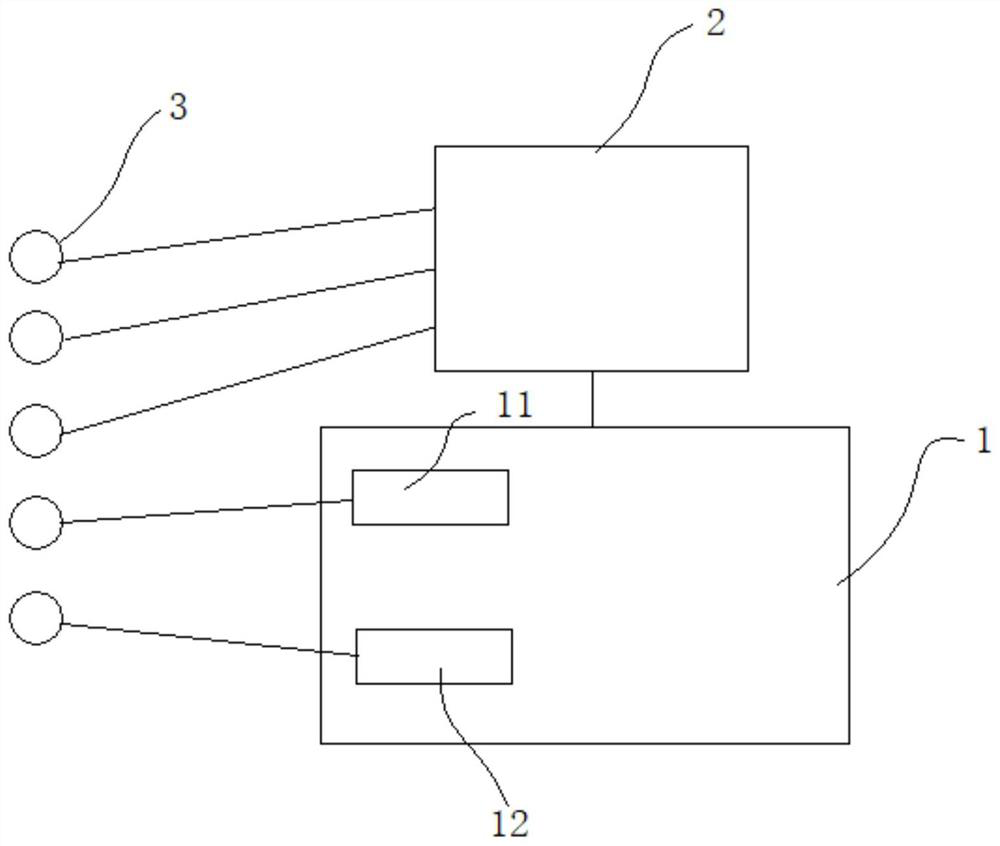
[0013] see figure 1 , a power distribution automation message monitoring device of the present invention includes an industrial computer 1 and a network port mirroring switch 2, which is used to monitor the message of the remote signaling device 3. The types of remote signaling equipment 3 include relays, DTU / RTU, protocol converters, encryption devices or switches.

[0014] Industrial computer 1 is the host computer. Part of the remote signaling device 3 is connected to the network port mirroring switch 2 with the network mirroring monitoring function and transmitted to the host, which can realize the monitoring of the messages transmitted in the connected network port. Some remote signaling devices 3 cannot be connected to the host computer when the mirroring function of the switch cannot be used. Therefore, correspond...


PUM


Abstract

The invention discloses a power distribution automation message monitoring device, and the device comprises an industrial personal computer, a network port mirror image switch, a serial port analyzer and a network port analyzer, wherein the industrial personal computer is connected with remote signaling equipment in a power distribution site; for remote signaling equipment capable of carrying out network port mirroring, a communication port of each piece of remote signaling equipment is transmitted to the industrial personal computer through a network port mirroring switch, and the network port mirroring switch carries out message transmission monitoring on the communication port of each mirroring access; for remote signaling equipment which cannot be subjected to network port mirroring, each peice of remote signaling equipment is accessed to the industrial personal computer, and a serial port analyzer and a network port analyzer are arranged in the industrial personal computer and are used for respectively monitoring transmission messages of each accessed network port and serial port. The system is used for realizing communication monitoring of remote signaling equipment among switch stations, power distribution stations, box transformers and in-station links.

Description

technical field [0001] The invention relates to a distribution automation message monitoring device used in the field of communication monitoring in the electric power industry. Background technique [0002] At present, in the power industry, communication message monitoring equipment is mainly used in substations, and there is no special monitoring device for the vast distribution network sites. The current message monitoring system mainly focuses on the communication between the plant station and the dispatching main station, and it is difficult to realize the communication between the switch station, distribution station, box transformer, and various links in the station. At present, as a large number of distribution network sites are connected to the dispatching system, a large number of false remote signals have occurred, resulting in false positives of the protection signal received by the dispatching end. The reason for the false positives is that links and equipment ...

Claims


Application Information

Patent Timeline
IPC IPC(8): H02J13/00
CPCH02J13/00002H02J13/00028
Inventor 董万新周翔沈主浮朱炯李中豪单文丽蒋凌芸张佳卓郁华陈思源蔡桢祺李佳文徐刚杨光李骁杰
Owner SHANGHAI MUNICIPAL ELECTRIC POWER CO
Why Eureka
Try Eureka