
Damping force adjustable shock absorber
A damping force and buffer technology, applied in the direction of shock absorbers, shock absorbers, liquid shock absorbers, etc., can solve the problem that the damping force in extremely low-speed areas cannot be adjusted
- Summary
- Abstract
- Description
- Claims
- Application Information
AI Technical Summary
Problems solved by technology
Method used
Image

Examples
no. 1 approach
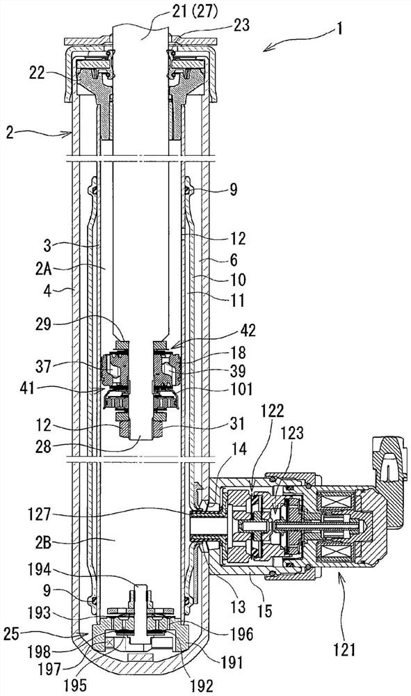
[0031] A first embodiment of the present invention will be described with reference to the drawings. For convenience, the figure 1 The up and down directions in are directly referred to as "up and down directions".
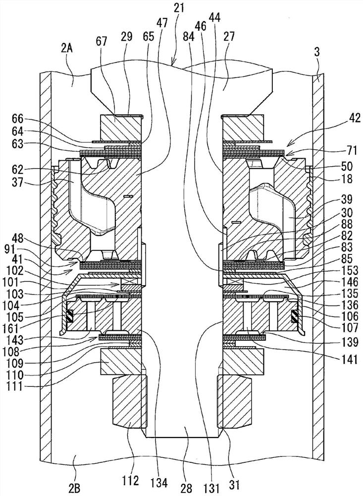
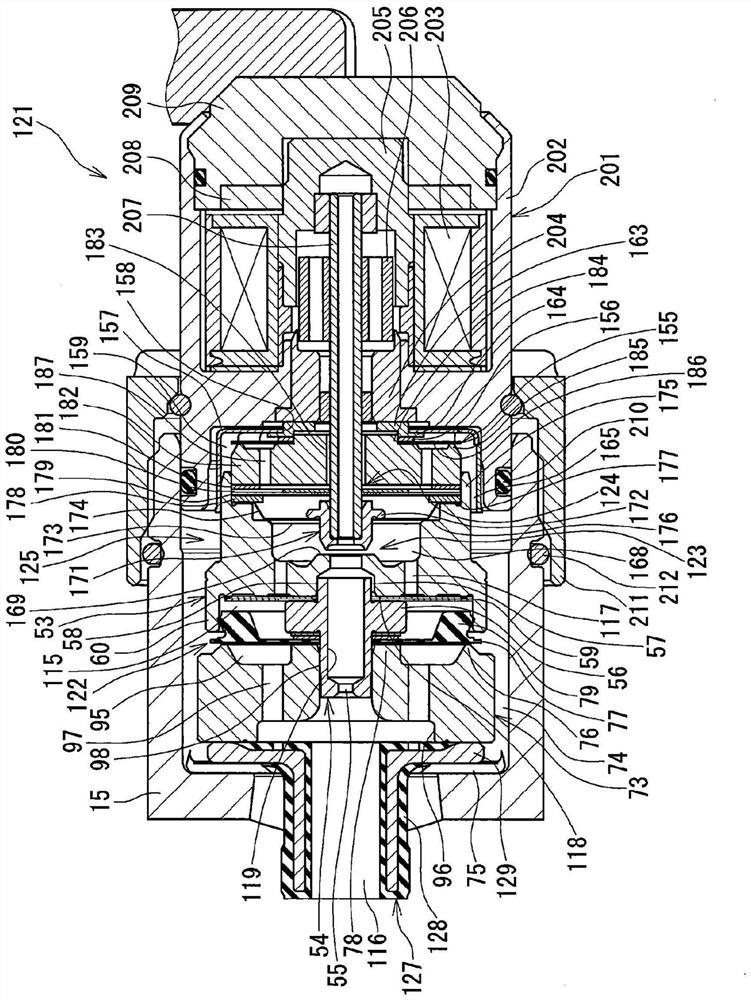
[0032] Such as figure 1 As shown, the damping force adjustable shock absorber 1 of the first embodiment is a so-called control valve laterally mounted type damping force adjustable shock absorber in which the damping force adjusting mechanism 121 is mounted laterally on the cylinder 2 . The cylinder 2 has an inner cylinder 3 and an outer cylinder 4 arranged coaxially with the inner cylinder. Between the inner cylinder 3 and the outer cylinder 4, a storage chamber 6 is formed. It should be noted that oil (working fluid) is sealed in the inner tube 3 , and oil and gas are sealed in the storage chamber 6 .
[0033] In the inner cylinder 3 of the cylinder 2, a piston 18 is slidably embedded, and the piston 18 divides the inner cylinder 3 into two cylinder upper ch...
no. 2 approach
[0093] Next, refer to Image 6 , Figure 7 A second embodiment will be described. Here, differences from the first embodiment will be described. It should be noted that the same designations and reference numerals are used for the same parts as those of the first embodiment, and overlapping descriptions will be omitted.
[0094] In the first embodiment, if Image 6 As shown, on the piston 18, the third passage 223 is provided in parallel with the inlet valve 71 (first low speed valve), and on the third passage 223, the micro low speed valve 108 (third low speed valve) on the extension side is arranged in parallel. valve) and a very low speed valve 105 (fifth low speed valve) on the compression side. Furthermore, the extremely low speed valves 108, 105 are arranged on the cylinder lower chamber 2B (second chamber) side with respect to the orifice 88 provided in the third passage 223 and communicating with the cylinder upper chamber 2A (first chamber). chamber) and cylinder...
no. 3 approach
[0098] Next, refer to Image 6 , Figure 8 A third embodiment will be described. Here, differences from the first embodiment will be described. It should be noted that the same designations and reference numerals are used for the same parts as those of the first embodiment, and overlapping descriptions will be omitted.
[0099] In the first embodiment, if Image 6 As shown, on the piston 18, the third passage 223 is provided in parallel with the inlet valve 71 (first low speed valve), and on the third passage 223, the micro low speed valve 108 (third low speed valve) on the extension side is arranged in parallel. valve) and a very low speed valve 105 (fifth low speed valve) on the compression side. Furthermore, the extremely low speed valves 108, 105 are arranged on the cylinder lower chamber 2B (second chamber) side with respect to the orifice 88 provided in the third passage 223 and communicating with the cylinder upper chamber 2A (first chamber). chamber) and cylinder ...
PUM
 Abstract
Description
Claims
Application Information