Damping force adjustment type shock absorber

A damping force and buffer technology, applied in shock absorbers, shock absorbers, liquid shock absorbers, etc., can solve problems such as the inability to adjust the damping force in extremely small and low-speed areas

Pending Publication Date: 2022-01-11
HITACHI ASTEMO LTD
View PDF2 Cites 0 Cited by
  • Summary
  • Abstract
  • Description
  • Claims
  • Application Information

AI Technical Summary

Problems solved by technology

Therefore, when the very low speed valve described in Patent Document 1 is applied only to the piston of the damping force adjustable shock absorber described in Patent Document 2, it takes time to generate a differential pressure to open the very low speed valve, and it cannot Adjusting the damping force in the very low speed range

Method used


Image

  • Damping force adjustment type shock absorber
  • Damping force adjustment type shock absorber
  • Damping force adjustment type shock absorber

Examples


no. 1 approach

[0024] A first embodiment of the present invention will be described with reference to the drawings. For convenience, the figure 1 The up and down directions in are directly referred to as "up and down directions".

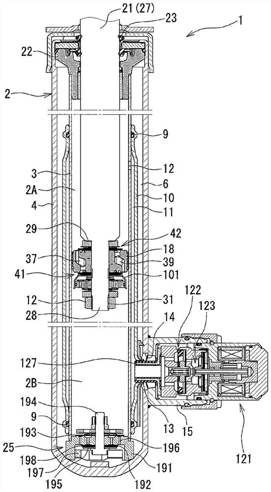
[0025] Such as figure 1 As shown, the damping force adjustable shock absorber 1 of the first embodiment is a so-called control valve laterally mounted type damping force adjustable shock absorber in which the damping force adjusting mechanism 121 is mounted laterally on the cylinder 2 . The cylinder 2 has an inner cylinder 3 and an outer cylinder 4 arranged coaxially with the inner cylinder 3 . Between the inner cylinder 3 and the outer cylinder 4, a storage chamber 6 is formed. It should be noted that oil (working fluid) is sealed in the inner tube 3 , and oil and gas are sealed in the storage chamber 6 .

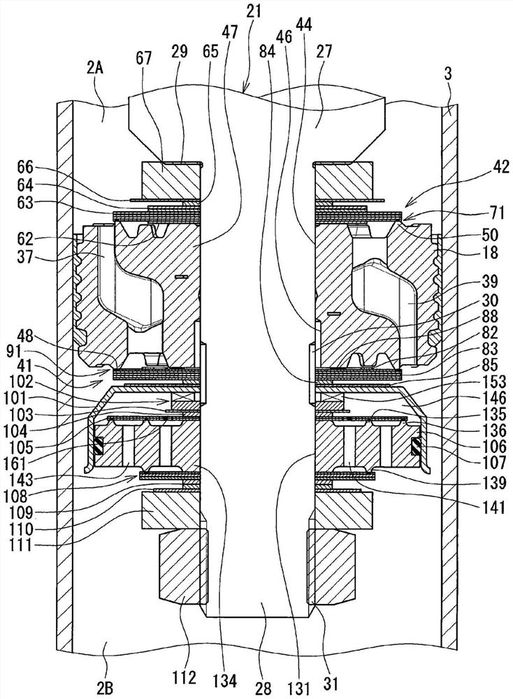
[0026] In the inner cylinder 3 of the cylinder 2, a piston 18 is slidably embedded, and the piston 18 divides the inner cylinder 3 into two cylinder upper...

no. 2 approach

[0088] Next, refer to Figure 7 A second embodiment will be described. Here, differences from the first embodiment will be described. It should be noted that the same designations and reference numerals are used for the same parts as those of the first embodiment, and overlapping descriptions will be omitted.

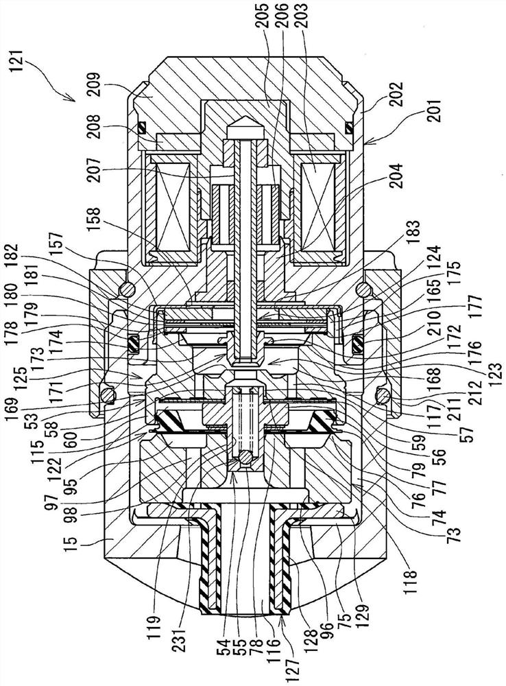
[0089] The first embodiment has a pilot pin 54 (introduction orifice forming member) in which an introduction orifice 55 is formed on a bottom portion 237 , and on the inner peripheral side of a cylindrical portion 238 of the pilot pin 54 (the shaft hole 119 of the pilot pin 54 ). , is equipped with a very small low-speed valve 231 (low-speed valve mechanism). In addition, in the first embodiment, the pilot chamber 115 is formed on the back side of the main disc valve 77 by bringing the packing 79 of the main valve 122 into slidable contact with the inner peripheral surface of the cylindrical portion 60 of the pilot body 53 . (back pressure chamber). That is, the ma...

no. 3 approach

[0100] Next, refer to Figure 8 A third embodiment will be described. Here, differences from the first embodiment and the second embodiment will be described. It should be noted that the same names and reference numerals are used for the common parts as those of the first embodiment and the second embodiment, and overlapping descriptions will be omitted.

[0101] In the damping force adjustment mechanism 242 of the second embodiment, the rigid body main valve 243 (the introduction orifice forming member) formed with the introduction orifice 55 is seated on the annular seat portion 76 formed in the main body 73 , thereby , a valve chamber 265 is formed between the main body 73 and the rigid body main valve 243 . In addition, in the second embodiment, the micro low speed valve 241 (low speed valve mechanism) having the micro low speed disc 258 is provided at the bottom 244 of the rigid main valve 243 .

[0102] In contrast, in the damping force adjustment mechanism 272 of the...


PUM


Abstract

In an ultra-low velocity region of piston velocity in a contraction stroke in a soft mode, communication between a cylinder upper chamber and a reservoir is shut off by means of an ultra-low velocity valve (low velocity valve mechanism) disposed in a pilot passage. By this means, liquid oil in the cylinder upper chamber can be caused to expand in the ultra-low velocity region of the contraction stroke, and a differential pressure is generated between the cylinder upper chamber side and a cylinder lower chamber side of the contraction side ultra-low velocity valve. As a result, the contraction side ultra-low velocity valve opens in the ultra-low velocity region, and a valve characteristic damping force due to the ultra-low velocity valve can be generated.

Description

technical field [0001] The present invention relates to a damping force adjustable damper that controls the flow of a working fluid accompanying the stroke of a piston rod to adjust a damping force. Background technique [0002] Patent Document 1 discloses a vibration absorber (shock absorber) including a very low-speed valve that opens in a very early low-speed region when the shock absorber starts to operate. In addition, Patent Document 2 discloses a so-called control valve lateral mounting type damping force adjustable shock absorber in which a damping force generating mechanism including a solenoid is laterally mounted on a side wall of an outer cylinder. [0003] In the damping force adjustable shock absorber described in Patent Document 2, the cylinder lower chamber is always in communication with the storage chamber through the orifice of the base valve. In addition, the pilot valve (control valve) of this damping force adjustable shock absorber is opened in the sof...

Claims


Application Information

Patent Timeline
Patent Type & Authority Applications(China)
IPC IPC(8): F16F9/18F16F9/32F16F9/34F16F9/348F16F9/36F16F9/44
CPCF16F9/18F16F9/32F16F9/34F16F9/3481F16F9/3484F16F9/36F16F9/44F16F9/348F16F9/465F16F9/46F16F2222/12F16F2228/066F16F2232/08F16F2234/02
Inventor 饭田朋彦门仓皓介门司健人森俊介
Owner HITACHI ASTEMO LTD
Why Eureka
Try Eureka