A kind of attenuation temperature drift method for digital oscilloscope and digital oscilloscope

A digital oscilloscope, attenuation network technology, applied in digital variable display, digital variable/waveform display, instruments, etc., to improve user experience and enhance the effect of waveform display

Active Publication Date: 2022-07-15
SHENZHEN CITY SIGLENT TECH
View PDF14 Cites 0 Cited by
  • Summary
  • Abstract
  • Description
  • Claims
  • Application Information

AI Technical Summary

Problems solved by technology

[0003] The technical problem mainly solved by the present invention is: how to attenuate the technical problem that the display waveform of the oscilloscope will produce temperature drift due to temperature changes

Method used


Image

  • A kind of attenuation temperature drift method for digital oscilloscope and digital oscilloscope
  • A kind of attenuation temperature drift method for digital oscilloscope and digital oscilloscope
  • A kind of attenuation temperature drift method for digital oscilloscope and digital oscilloscope

Examples


Embodiment 1

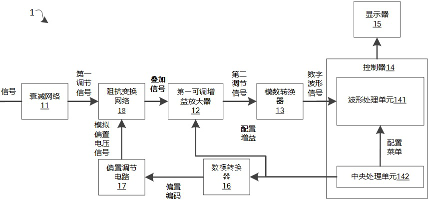
[0052] Please refer to Figure 5, is a schematic structural diagram of a digital oscilloscope in another embodiment. The digital oscilloscope 1 includes a controller 14 , an attenuation network 11 , an impedance transformation network 18 , a first adjustable gain amplifier 12 , an analog-to-digital converter 13 , and an offset adjustment circuit 17 . , bias gain circuit 19 , digital to analog converter 16 and display 15 . The attenuation network 11 is connected to the impedance transformation network 18 . The attenuation network 11 is used to attenuate the input signal VIN input to the digital oscilloscope 1 to obtain the first adjustment signal VIN1 and output the first adjustment signal VIN1 to the impedance transformation network 18 . The digital-to-analog converter 16 is respectively connected with the controller 14 and the offset adjustment circuit 17, and the digital-to-analog converter 16 is used for converting the offset code of a digital signal output by the controlle...

Embodiment 2

[0075] Please refer to Image 6 , is a schematic flowchart of a method for attenuating temperature drift for a digital oscilloscope in another embodiment. The digital oscilloscope includes an impedance transformation network, a bias adjustment circuit and an attenuation network, and the method for attenuating temperature drift includes:

[0076] Step 100, obtaining the vertical scale setting value of the digital oscilloscope;

[0077] Step 200, adjusting the bias voltage signal;

[0078] Attenuate or amplify the bias voltage signal output by the bias adjustment circuit of the digital oscilloscope according to the vertical scale setting value, and output the attenuated or amplified bias voltage signal to the impedance transformation network, so that the impedance transformation network will attenuate or amplify the bias voltage signal. The amplified bias voltage signal is superimposed with the output signal of the attenuation network of the digital oscilloscope, so that the te...


PUM


Abstract

The present application discloses an attenuation temperature drift method and a digital oscilloscope for a digital oscilloscope. The digital oscilloscope includes an impedance transformation network, an attenuation network and an offset adjustment circuit. First obtain the vertical scale setting value of the digital oscilloscope; then attenuate or amplify the bias voltage signal output by the bias adjustment circuit according to the vertical scale setting value, and output the attenuated or amplified bias voltage signal to the impedance transformation network , so that the impedance transformation network superimposes the attenuated or amplified bias voltage signal and the output signal of the attenuation network, so that the temperature drift phenomenon when the digital oscilloscope displays the waveform is attenuated. Since the bias voltage signal is adjusted according to the vertical scale setting value, the temperature drift phenomenon is attenuated, thereby enhancing the waveform display effect of the digital oscilloscope to improve user experience.

Description

technical field [0001] The invention relates to the technical field of oscilloscopes, in particular to an attenuation temperature drift method for a digital oscilloscope and a digital oscilloscope. Background technique [0002] Digital oscilloscopes are an indispensable tool for designing, manufacturing and maintaining electronic equipment. Today's oscilloscopes are mostly digital oscilloscopes, which are increasingly popular due to their functions such as waveform triggering, storage, display, measurement, and analysis. With the rapid development of digital oscilloscopes, digital oscilloscopes are considered to be the eyes of engineers, which will be used as a necessary tool to meet the measurement challenges of engineers. Especially in the development process of electronic circuits, oscilloscopes are often used for debugging and measurement, and the measurement accuracy is getting higher and higher, and the performance requirements of oscilloscopes are getting higher and h...

Claims


Application Information

Patent Timeline
Patent Type & Authority Patents(China)
IPC IPC(8): G01R13/02
CPCG01R13/02G01R13/0218
Inventor 曾显华陈滨慰谢炳涛
Owner SHENZHEN CITY SIGLENT TECH
Why Eureka
Try Eureka