Automatic powder spraying device of glass lining equipment

A glass-lined and powder-spraying technology, which is applied in the field of automatic powder-spraying devices, can solve problems such as inability to spray powder on tanks of different sizes, uneven powder spraying, and increased production costs, and achieve flexible use, good spraying effects, and streamlined production The effect of craft

Pending Publication Date: 2022-08-02
临沂市海鑫化工设备有限公司
View PDF5 Cites 1 Cited by
  • Summary
  • Abstract
  • Description
  • Claims
  • Application Information

AI Technical Summary

Problems solved by technology

[0003] The existing automatic powder spraying device for glass-lined equipment is not evenly sprayed, the powder spray effect is poor, and it is impossible to spray powder on tanks of different sizes, which increases the production cost

Method used


Image

  • Automatic powder spraying device of glass lining equipment
  • Automatic powder spraying device of glass lining equipment
  • Automatic powder spraying device of glass lining equipment

Examples


Embodiment 1

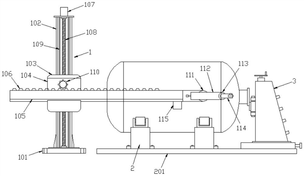
[0023] Example 1: see figure 1 , the present invention provides a technical solution: an automatic powder spraying device for glass-lined equipment, comprising a powder spraying support mechanism 1, a tank body support mechanism 2 and a tank body anti-channeling mechanism 3; the powder spraying support mechanism 1 includes a first The base 101, the top of the first base 101 is fixed with a vertical rod 102, the external sliding sleeve of the vertical rod 102 is provided with a lifting block 103, and the lifting block 103 is driven by a lifting mechanism; The front side is provided with a first chute 104, the first chute 104 is provided with a boom telescopic shaft 105, and the bottom end of the boom telescopic shaft 105 is slidably connected to the inner bottom wall of the first chute 104. A rack 106 is provided on the top of the boom telescopic shaft 105, and the rack 106 is driven by a gear mechanism.

[0024] In this embodiment, the lifting mechanism includes a lifting mot...

Embodiment 2

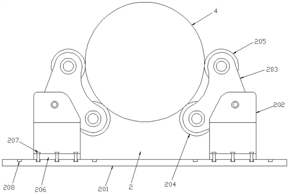
[0029] Example 2: see figure 2 , the tank body support mechanism 2 is used to support the tank body 4, the tank body support mechanism 2 includes a second base 201, and the top of the second base 201 is provided with four moving seats 202 in a rectangular array, so An enclosing frame 203 is installed on the movable seat 202 , a numerical control driving wheel 204 is installed at the bottom of the surrounding frame 203 , and a guide wheel 205 is installed at the top of the surrounding frame 203 ; the bottoms of both sides of the movable seat 202 are fixedly connected There is a fixing plate 206 on which a tightening bolt 207 is movably arranged, and the head end of the tightening bolt 207 is threadedly connected with a reserved hole 208 opened on the upper surface of the second base 201, and the reserved hole 208 is provided There are several, several reserved holes 208 are divided into 8 groups, and each group is arranged in a linear array.

[0030]The movable seat 202 is fi...

Embodiment 3

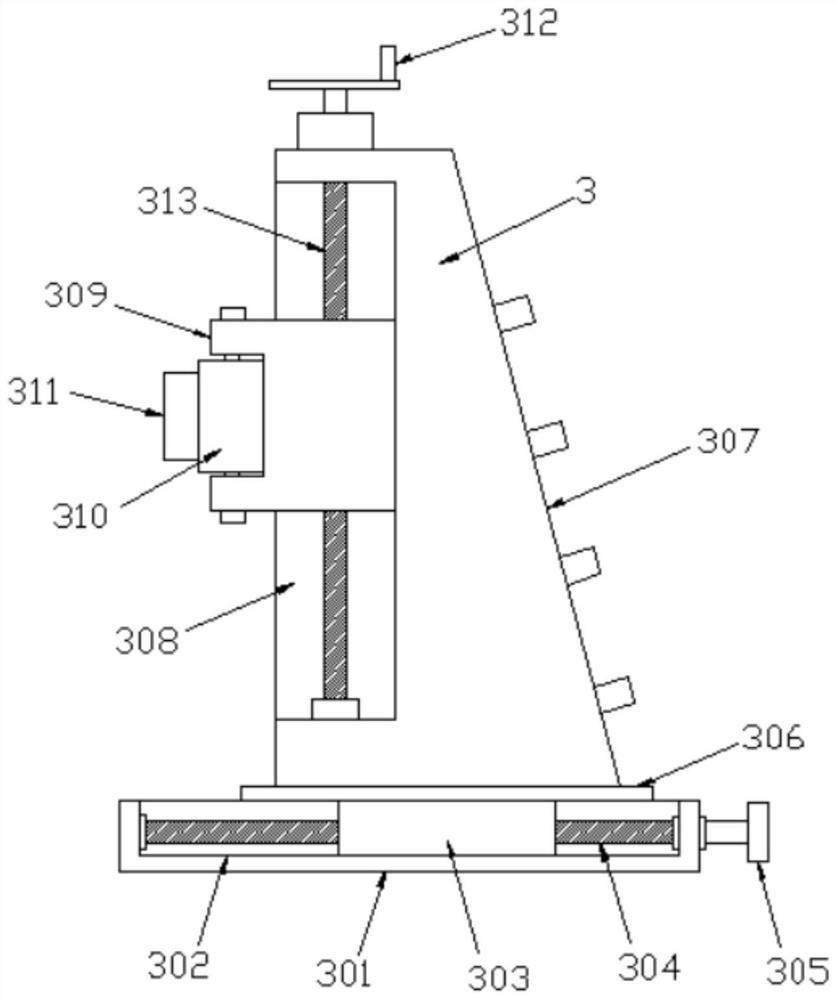
[0031] Example 3: see image 3 , the tank anti-channeling mechanism 3 includes a third base 301, the third base 301 is fixed on the top of the second base 201, the top of the third base 301 is provided with a moving groove 302, and the moving groove 302 A moving block 303 is slidably connected inside, and a second screw rod 304 is screwed through the moving block 303. One end of the second screw rod 304 is rotatably connected with the inner wall of the moving groove 302, and the other end is movable through the moving groove 302 and fixed. The first hand wheel 305 is connected; the top of the moving block 303 is fixed with a moving plate 306, the bottom of the moving plate 306 is slidably connected with the top of the third base 301, and the top of the moving plate 306 is fixed with a base 307, The side of the base 307 facing the tank body support mechanism 2 is provided with a second chute 308 , and a mounting block 309 is slidably connected in the second chute 308 , and the ...


PUM


Abstract

The invention belongs to the technical field of glass-lined tank production, and particularly discloses an automatic powder spraying device of glass-lined equipment, which comprises a powder spraying support mechanism, a tank body support mechanism and a tank body anti-channeling mechanism, the powder spraying supporting mechanism comprises a first base, the top end of the first base is fixedly connected with a vertical rod, and the vertical rod is slidably sleeved with a lifting block; a first sliding groove is formed in the front side of the lifting block, a large arm telescopic shaft is arranged in the first sliding groove, the bottom end of the large arm telescopic shaft is slidably connected with the inner bottom wall of the first sliding groove, a rack is arranged at the top of the large arm telescopic shaft, and the tank body supporting mechanism is used for supporting a tank body and comprises a second base. Four moving seats are arranged on the top of the second base in a rectangular array mode, a surrounding frame is installed on the moving seats, numerical control driving wheels are installed at the bottom of the surrounding frame, and guide wheels are installed at the top of the surrounding frame; the spraying device is good in spraying effect and capable of spraying can bodies of different sizes, and the production cost is reduced.

Description

technical field [0001] The invention relates to the technical field of glass-lined tank production, in particular to an automatic powder spraying device for glass-lined equipment. Background technique [0002] Glass-lined jars are widely used in people's lives, medicine, chemicals, pesticides, sewage treatment, electronics, etc. due to their excellent properties such as safety, non-toxicity, easy washing and cleaning, high hardness, high temperature resistance, wear resistance, corrosion resistance and insulation. In many fields, the market demand is huge every year, and one of the key links in the production process of glass-lined cans is electrostatic spray dry powder. [0003] When the automatic powder spraying device of the existing glass-lined equipment is used, the powder spraying is not uniform enough, the powder spraying effect is poor, and the powder spraying can not be performed on the tanks of different sizes, which increases the production cost. SUMMARY OF THE ...

Claims


Application Information

Patent Timeline
Patent Type & Authority Applications(China)
IPC IPC(8): B05B5/08B05B5/12B05B14/10B05B13/06
CPCB05B5/081B05B5/12B05B5/082B05B14/10B05B13/0681B05B13/0627Y02P70/10
Inventor 周荣升王明政袁俊杰焦方芳秦显熙
Owner 临沂市海鑫化工设备有限公司
Why Eureka
Try Eureka