Cell

A battery and power collection technology, applied in dry batteries, secondary batteries, lead-acid batteries, etc., can solve problems such as reducing battery performance

Inactive Publication Date: 2006-01-18
GS YUASA INT LTD
View PDF1 Cites 2 Cited by
  • Summary
  • Abstract
  • Description
  • Claims
  • Application Information

AI Technical Summary

Problems solved by technology

This reduces bat

Method used


Image

  • Cell
  • Cell
  • Cell

Examples


Embodiment Construction

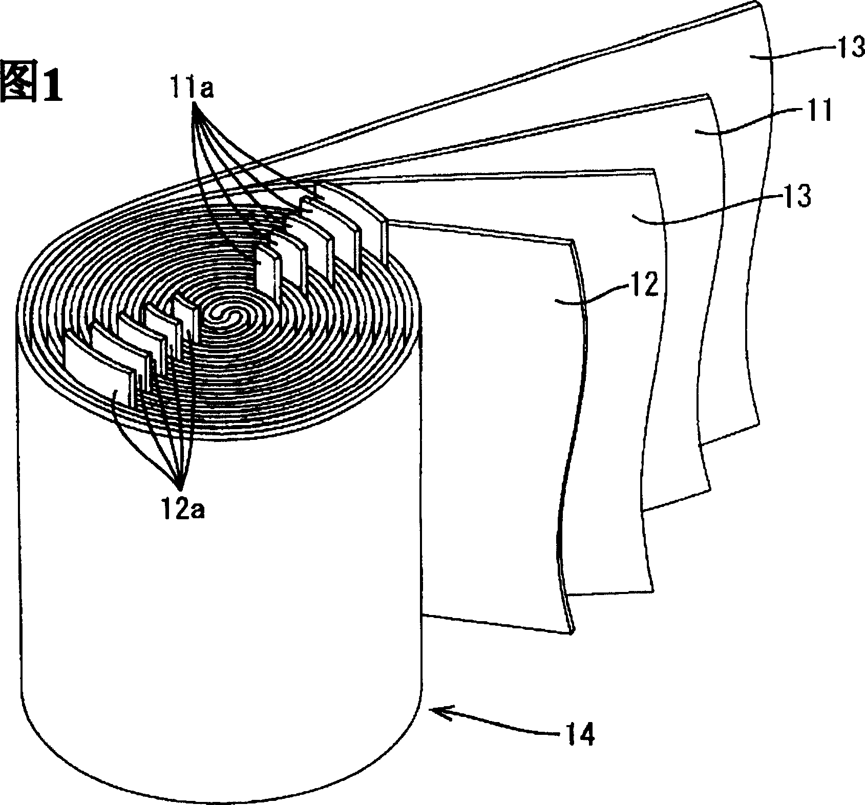
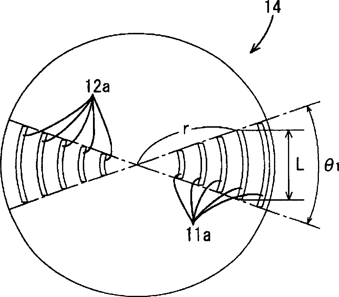
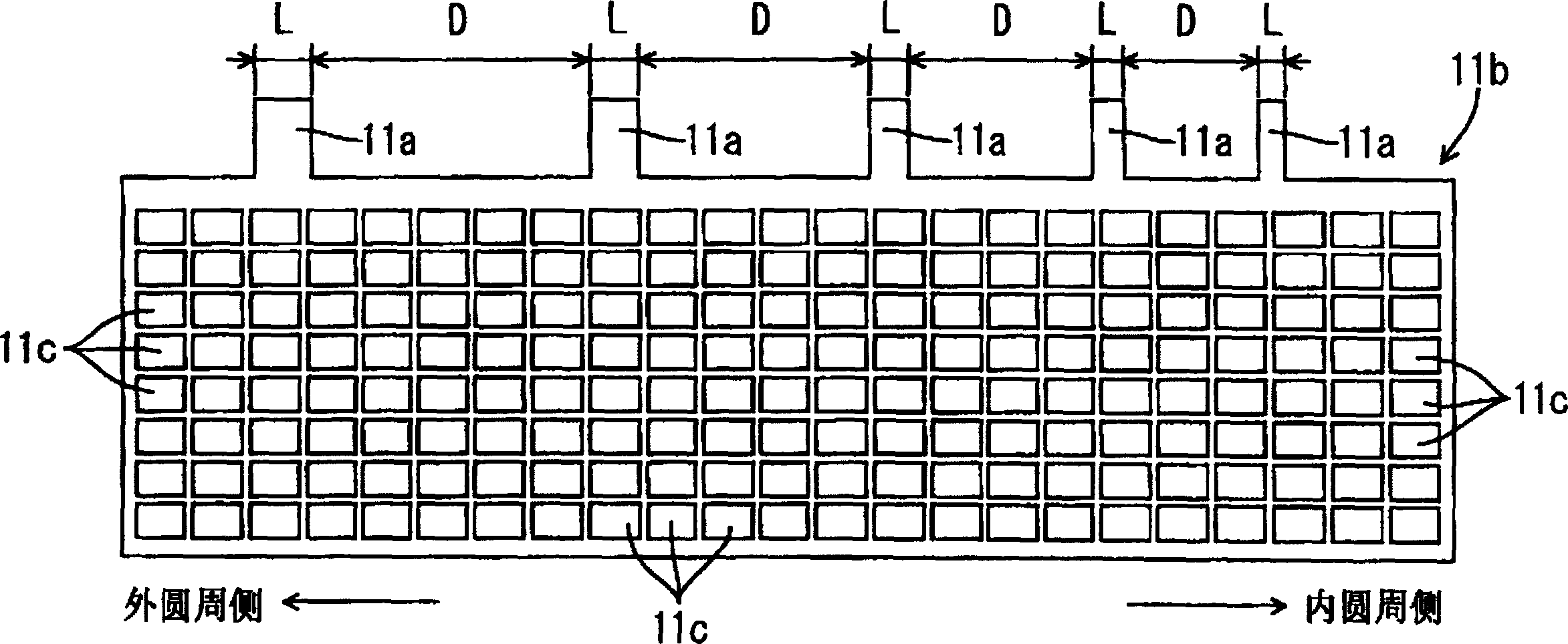
[0029] A cylindrical lead storage battery as an embodiment of the present invention will be explained below with reference to the accompanying drawings. The power generating element 14 of the lead storage battery is a cylindrical structure, which consists of the strip-shaped positive electrode 11 and the strip-shaped negative electrode 12 and the strip-shaped separator layer 13 are spirally wound together from the beginning to the end. As shown in FIG. 1, the coil-formed power generating element 14 has collector tabs 11a and 12a protruding from its upper portion, and is arranged along a straight line passing through the center of the coil. The current collector tab 11a of the positive electrode 11 is arranged in half of the straight line, that is, on one side of the winding center, while the current collector tab 12a of the negative electrode 12 is arranged in the other half. That is, the current collecting tabs 11a and 12a are arranged such that the current collecting tab on ...


PUM


Abstract

A battery comprising an electricity-generating element comprising a strip-form positive electrode (11), a strip-form negative electrode (12), and a strip-form separator (13), said positive electrode and said negative electrode being spirally wound through said separator and said positive electrode and said negative electrode respectively having current collecting lugs (11a,12a) protruding from a side thereof, wherein the pitches of the current collecting lugs become longer toward the outer periphery side, and the at least one current collecting lug that located on the outer side has a larger width than that located on the inner side. In this battery, the electricity-generating element has at least one current collecting lug which has a larger width than the adjacent current collecting lug located on the inner side thereof. Consequently, although the current collecting lugs in an outer region are located at a longer pitch and the area to be covered by each current collecting lug in that region is wide, charge/discharge current can sufficiently flow through the active material throughout the whole area in that region. Therefore, charge/discharge current can evenly flow through the electrodes including their inner and outer parts, whereby the active materials can have an even reaction distribution.

Description

technical field [0001] The present invention relates to batteries. Background technique [0002] The preparation of cylindrical lead storage battery can be by, for example, strip-shaped positive pole 21 and negative pole 22 are spirally wound together with strip-shaped diaphragm layer 23 to form cylindrical power generation element 24 (as shown in Figure 6), and this element 24 is embedded battery case (not shown in the figure), and seal the case. [0003] The power generating element 24 is formed by winding a collector tab 21a and a collector tab 22a, the collector tabs protrude from the top of the element 24, and are arranged along a straight line passing through the center of the coil. The current collecting tab 21a of the positive electrode 21 is provided on one half of the straight line, ie, one side of the winding center, while the current collecting tab 22a of the negative electrode 22 is provided on the other half. That is, the collector tabs 21a and 22a are arrang...

Claims


Application Information

Patent Timeline
IPC IPC(8): H01M4/64H01M4/14H01M10/06H01M10/00H01M6/10H01M10/04H01M10/12H01M50/538
CPCY02E60/12H01M2/263H01M10/0431H01M6/10Y02E60/126Y02E60/10H01M50/538Y02P70/50
Inventor 久井真
Owner GS YUASA INT LTD
Why Eureka
Try Eureka