Discharge lamp with helical discharge tube

A discharge tube, helical technology, applied in the field of low-pressure discharge lamps, to achieve the effects of avoiding bad connections, enhancing mechanical stability, and improving brightness distribution

Inactive Publication Date: 2006-11-22
GENERAL ELECTRIC CO
View PDF1 Cites 1 Cited by
  • Summary
  • Abstract
  • Description
  • Claims
  • Application Information

AI Technical Summary

Problems solved by technology

However, especially since in the direction along the axis of the discharge lamp and towards the end away from the lampholder, a large part of this envelope surface is not used as a light-emitting surface, the light intensity distribution of this lamp in the vicinity of the low-temperature chamber remains the same. need to improve

Method used


Image

  • Discharge lamp with helical discharge tube
  • Discharge lamp with helical discharge tube
  • Discharge lamp with helical discharge tube

Examples


Embodiment Construction

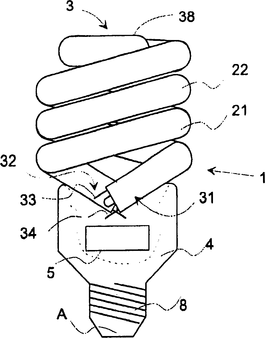
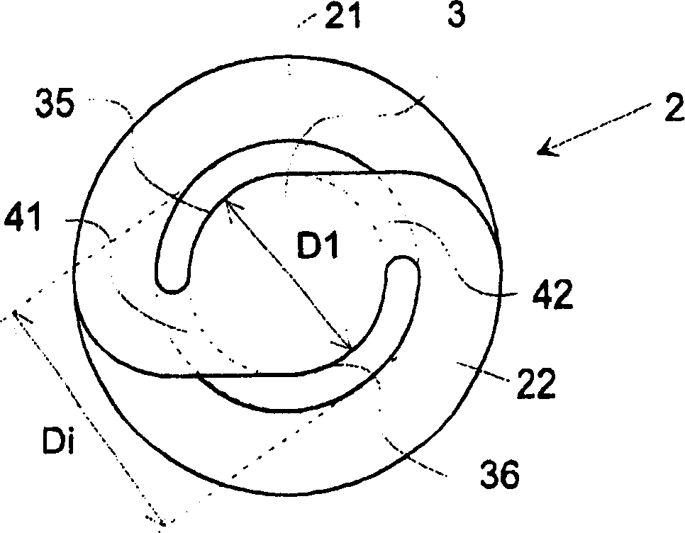
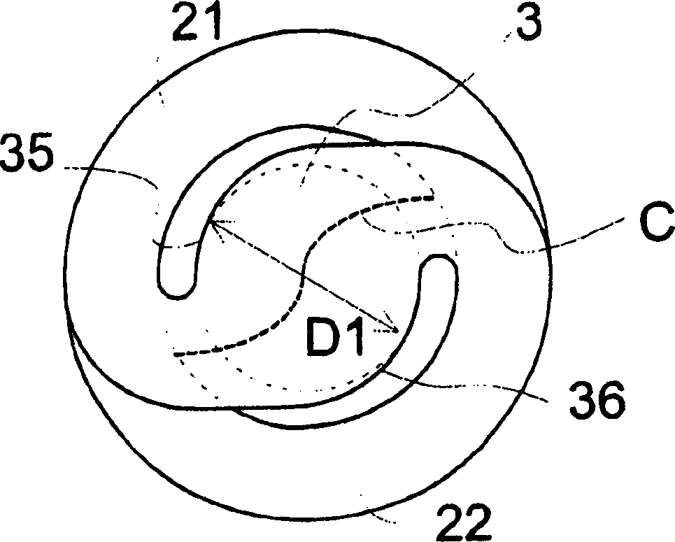
[0015] now refer to figure 1 and 2 , a low-pressure arc discharge lamp 1 is shown here. The discharge vessel 2 of the discharge lamp 1 has sealed ends 31 , 32 . figure 1 The discharge lamp 1 in has two helical discharge vessel parts 21 and 22 which are connected to each other by a low temperature chamber part 3 at the upper ends of the discharge vessel parts 21 and 22 .

[0016] The discharge tube 2 is mechanically supported by the lamp holder 4 . The lamp holder 4 surrounds the sealed ends 31 , 32 of the discharge vessel 2 . More precisely, the sealed ends 31 , 32 of the discharge tube parts 21 , 22 are inside the lamp holder 4 , while the main parts of the discharge tube parts 21 , 22 are outside the lamp holder 4 . The discharge lamp 1 is of the type that emits light from a layer of phosphor deposited on the inner surface of the discharge vessel 2, which phosphor is excited by the discharge arc. Electrons for the arc are emitted from a heated filament (not shown). The...


PUM


Abstract

A low-pressure discharge lamp with a double helical discharge vessel (2) comprising two helical discharge vessel parts (21, 22). The discharge vessel portions (21, 22) define a central axis (A) of the discharge vessel (2). The cryogenic chamber section (3) connects the ends of the spiral discharge tube sections (21, 22). The first transverse dimension (D1) of the cryogenic chamber section (3) is substantially perpendicular to the central axis (A), which transverse dimension is larger than the diameter (d) of the discharge tube sections (21, 22). The low temperature chamber section (3) additionally has a second transverse dimension (D2) substantially parallel to the central axis (A). The second transverse dimension (D2) of the cryogenic chamber section (3) substantially corresponds to the diameter (d) of the discharge vessel section (21, 22).

Description

technical field [0001] The invention relates to a low-pressure discharge lamp comprising a double helical discharge vessel comprising two helical discharge vessel parts. The discharge lamp is provided with a low temperature chamber section connecting the ends of the spiral discharge tube section. Background technique [0002] Low-pressure discharge lamps are well known in the art. These discharge lamps contain a small dose of mercury which glows under the action of the discharge arc. To obtain maximum light output, the mercury vapor needs to be controlled and stabilized at a well-defined partial pressure. It is possible to control and stabilize the mercury vapor by making a so-called cryo-chamber on the discharge tube and choosing an appropriate temperature in the cryo-chamber, which is the coldest point in the gas discharge tube. [0003] In the patent No. DD 212 843 issued by the former German Democratic Republic, a small spiral fluorescent lamp is disclosed. The fluor...

Claims


Application Information

Patent Timeline
Patent Type & Authority Patents(China)
IPC IPC(8): H01J61/30H01J61/42H01J17/16H01J17/20H01J61/12H01J61/33H01J61/72
CPCH01J61/33H01J61/72
Inventor L·伊尔耶斯J·托克斯J·福洛普
Owner GENERAL ELECTRIC CO
Why Eureka
Try Eureka