Pan head

A cloud platform and mounting body technology, applied in the field of cloud platform, can solve the problems of insufficient miniaturization and achieve the effect of ensuring miniaturization, good operability and convenient assembly

Inactive Publication Date: 2007-05-16
VELBON
View PDF4 Cites 0 Cited by
  • Summary
  • Abstract
  • Description
  • Claims
  • Application Information

AI Technical Summary

Problems solved by technology

[0011] However, in the pan / tilt of the above-mentioned structure shown in FIG. 9 , the front surface of the support plate portion 2 a of the tilting body 2 protrudes forward to form a side tilt axis 3 in the front and rear horizontal direction, and the camera mounting body 4 is provided on the side protruding forward. On the tilt axis 3, there is no space on the front side of the upper part of the gimbal, and the gimbal cannot be sufficiently miniaturized when it is not in use, such as being carried.

Method used


Image

  • Pan head
  • Pan head
  • Pan head

Examples


Embodiment Construction

[0030] Embodiments of the cloud platform of the present invention will be described below with reference to the accompanying drawings.

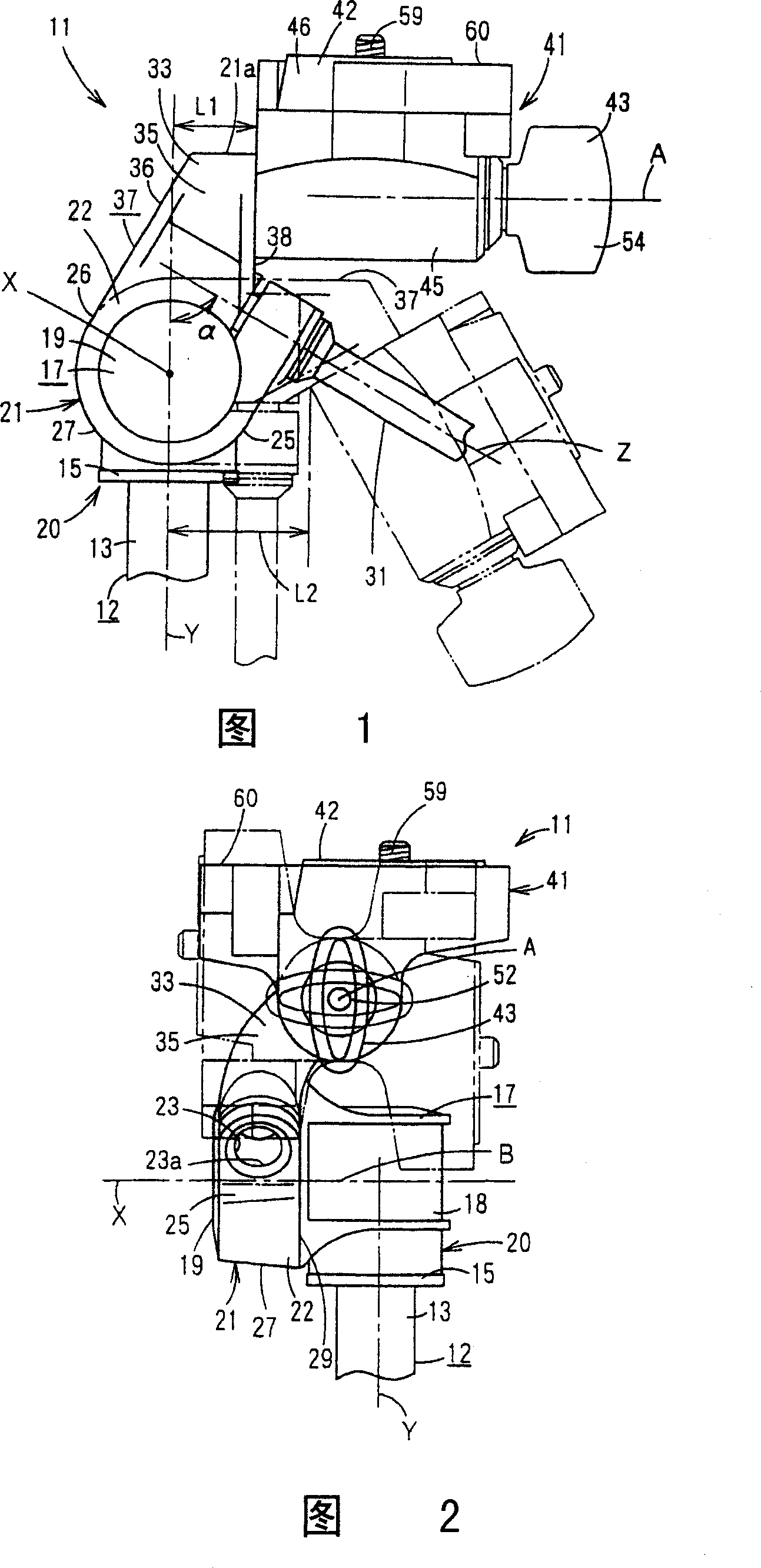
[0031] Fig. 1 to Fig. 5 show the overall condition of the pan-tilt 11 under the reference state, this pan-tilt 11 is for example installed on the pan-tilt mounting part 13 that is formed on the tripod 12 upper end portion of the camera tripod etc., to fix not shown in the figure. Therefore, utilizing the function of the platform 11, the camera lens can be set in any direction up, down, left, and right according to the position of the photographed scene under the state of fixing the tripod device 12.

[0032] As shown in Figure 5, this cloud platform 11 has a lower end portion made into a substantially cylindrical tripod connecting member 15 with a large diameter, and a threaded hole 16 as a connecting hole is formed on the bottom surface of the tripod connecting member 15. The hole 16 is screwed with an unillustrated male screw thread on the ...


PUM


Abstract

A pan head (11) comprising a base body (20) connected to a leg device (12), a tilt rotary body (21) rotationally adjustable around a horizontal rotation axis (X), and a camera attaching body (41) rotationally adjustable around a transverse horizontal rotation axis (A) axially aligned with a side tilt shaft. The rotation axis (A) of the camera attaching body (41) substantially coincides with the longitudinal centerline (B) of a base body (20), as seen in a plan view. The side tilt shaft is positioned substantially below the level of the camera fixing screw (59) of the camera attaching body (41).

Description

technical field [0001] The present invention relates to a pan / tilt mounted on a tripod such as a camera tripod. Background technique [0002] Conventionally, there is a pan-tilt shown in FIG. 7, a pan-tilt shown in FIG. 8, or the like. [0003] First, the cloud platform in FIG. 7 has a tilting body 2 that is rotatably and adjustablely installed on the base body 1, and has a camera mounting body 4 pivotally supported on the side tilting shaft 3 of the tilting body 2. The camera mounting body The bolt 6 of large-diameter head 5 is housed on 4. [0004] In the cloud platform of Fig. 7, hand is stretched in the space 7 between the top of base body 1 and the bottom of camera mounting body 4, pinches the head 5 of bolt 6, and the front end side of bolt 6 is connected with camera (not shown). ) is screwed into the bottom surface of the threaded hole, so that the camera is mounted on the camera mounting body 4. [0005] The cloud platform of Fig. 8 has the tilt rotating body 2 th...

Claims


Application Information

Patent Timeline
Patent Type & Authority Patents(China)
IPC IPC(8): G03B17/56F16M11/04F16M11/06F16M11/12H04N5/222
CPCF16M11/10F16M11/06G03B17/56F16M11/041F16M11/12F16M11/2014F16M11/04F16M13/00G03B17/561G03B17/563
Inventor 中谷幸一郎
Owner VELBON
Why Eureka
Try Eureka