Solid electrolyte type fuel cell

A solid electrolyte, fuel cell technology, applied in solid electrolyte fuel cells, fuel cells, fuel cell additives, etc., can solve problems such as changes and achieve the effect of efficient operation

Inactive Publication Date: 2009-04-01
DAIKIN IND LTD
View PDF5 Cites 0 Cited by
  • Summary
  • Abstract
  • Description
  • Claims
  • Application Information

AI Technical Summary

Problems solved by technology

However, the flow rate of the air flowing through the air passage for heat recovery cannot be changed relative to the full flow rate in response to such a request.

Method used


Image

  • Solid electrolyte type fuel cell
  • Solid electrolyte type fuel cell
  • Solid electrolyte type fuel cell

Examples


Embodiment Construction

[0034] Hereinafter, embodiments of the solid electrolyte fuel cell of the present invention will be described in detail with reference to the drawings.

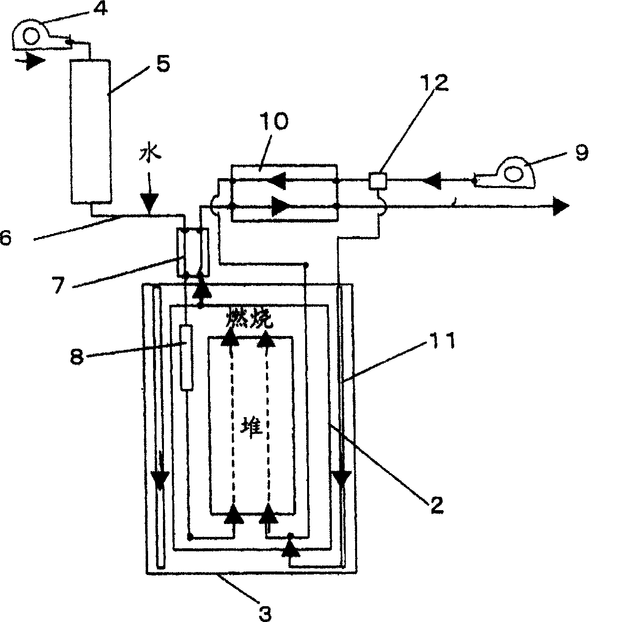
[0035] figure 1 It is a schematic diagram showing one embodiment of the solid electrolyte fuel cell of the present invention.

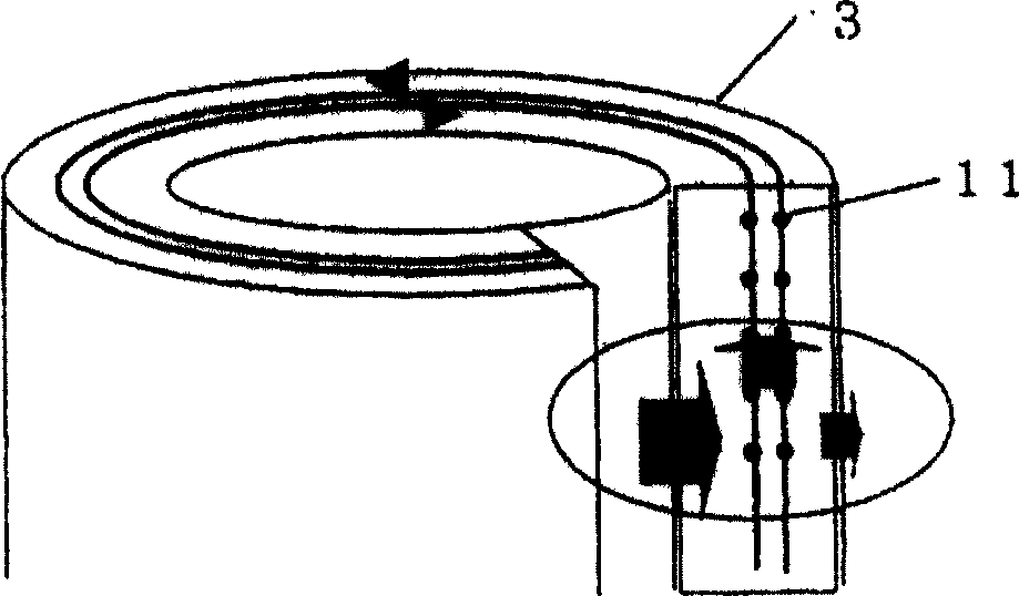
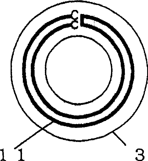
[0036] This solid electrolyte fuel cell has: a fuel cell stack 1; a storage container 2 that houses the fuel cell stack 1; a heat insulating material member 3 that surrounds the storage container 2; a fuel gas supply source 4; a desulfurizer 5 that receives fuel gas and undergoes desulfurization treatment; a water adding part 6, which adds water to the output of the desulfurizer 5 (desulfurized fuel gas); a gasifier 7, which performs heat exchange between the combustion gas from the fuel cell stack 1, And the desulfurized fuel gas added with water is gasified; reformer 8, which reforms the gasified desulfurized fuel gas added with water, and provides it to the fuel cell stack 1; air supply source 9;...


PUM


Abstract

A solid electrolyte type fuel cell, comprising a branch flow rate regulating part (12) for branching air between an air supply source (9) and a heat exchanger (10), leading the branched air to a heat recovery passage (11), and regulating the branched air amount to properly control the flow of a fluid flowing to a flow passage for heat recovery to the total of the flow.

Description

technical field [0001] The present invention relates to a solid electrolyte fuel cell configured by housing a solid electrolyte fuel cell stack in a storage container. Background technique [0002] Conventionally, a fuel cell has been proposed (see Patent Document 1 and Patent Document 2) in which a heat recovery passage for recovering heat lost from the battery module is provided around the battery module, wherein the battery module The inside of the stack includes: a cell stack that generates electricity from fuel gas and oxygen-containing gas; and a combustion unit that burns excess fuel gas and oxygen-containing gas from the cell stack in contact with each other. [0003] The solid electrolyte fuel cell described in Patent Document 1 is constituted by forming a fluid channel between a high-temperature heat insulating material and a low-temperature heat insulating material surrounding the fuel cell stack, and supplying air to the air inlet port of the fuel cell stack thro...

Claims


Application Information

Patent Timeline
Patent Type & Authority Patents(China)
IPC IPC(8): H01M8/04H01M8/12H01M8/06
CPCH01M8/0612H01M8/2475H01M8/04067H01M8/04022H01M8/12H01M8/04126Y02E60/521H01M8/04089Y02E60/525H01M8/0675Y02E60/50
Inventor 川添政宣松井伸树米本和生
Owner DAIKIN IND LTD
Why Eureka
Try Eureka