Sagnac interferometer type current sensor

A technology of current sensor and interferometer, which is applied in the direction of instrumentation, voltage/current isolation, measurement of current/voltage, etc. It can solve the problems that coherent light is difficult to obtain modulation amplitude and propagation time difference

Inactive Publication Date: 2002-12-18
JAPAN AVIATION ELECTRONICS IND LTD +1
View PDF2 Cites 18 Cited by
  • Summary
  • Abstract
  • Description
  • Claims
  • Application Information

AI Technical Summary

Problems solved by technology

When the detection coil 6 has an optical fiber length on the order of 10 meters, a sufficient propagation time difference cannot be obtained between the left-handed and right-handed light, and thus it is difficult to obtain a sufficient modulation amplitude for the resulting coherent light

Method used


Image

  • Sagnac interferometer type current sensor
  • Sagnac interferometer type current sensor
  • Sagnac interferometer type current sensor

Examples


Embodiment Construction

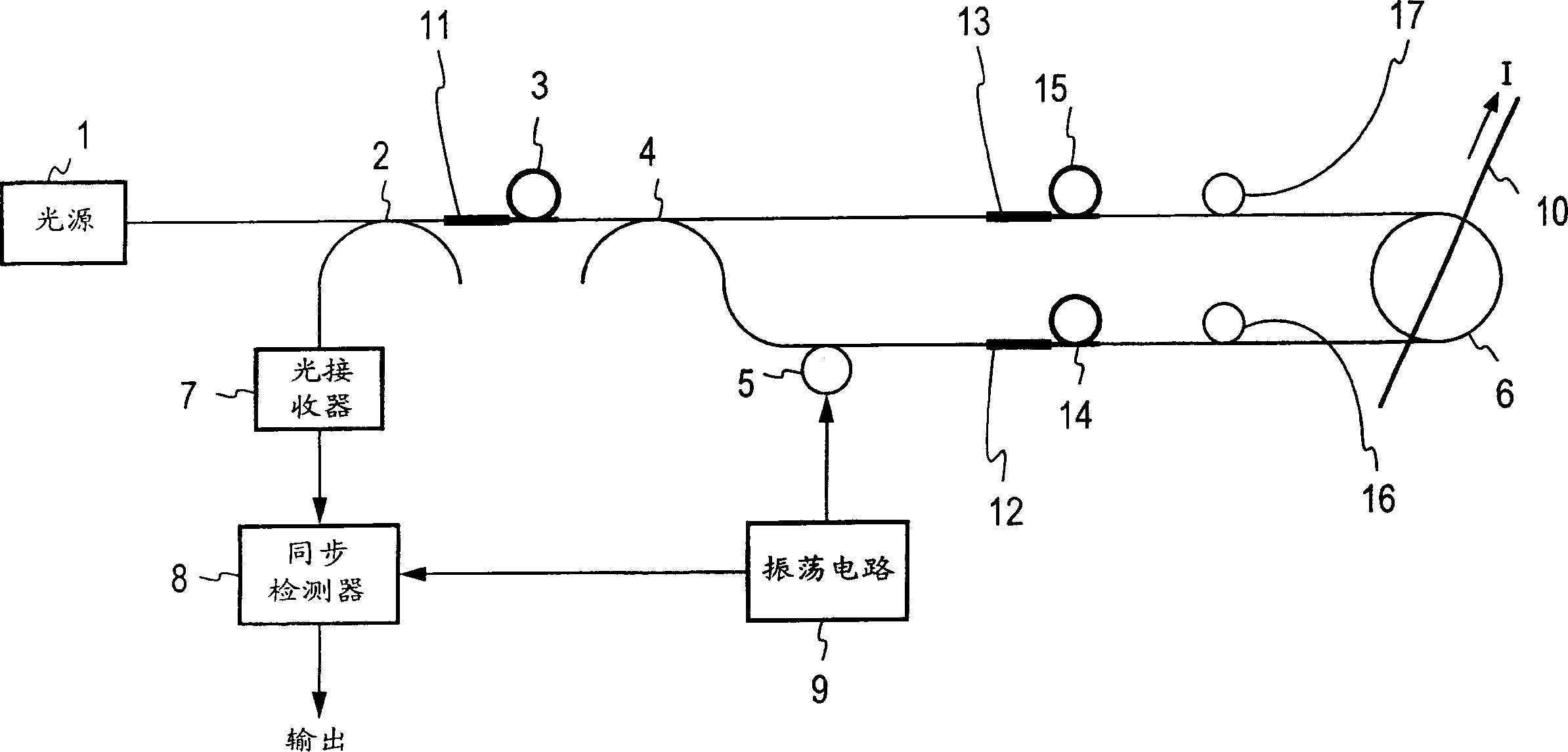
[0029] will refer to image 3 The illustrated embodiments describe modes of carrying out the invention.

[0030] exist image 3 in and in figure 1 Corresponding parts to those shown are designated by the same reference numerals as previously used. In this embodiment, the fiber connecting the optics is constructed of single-mode fiber, and a depolarizer is used to receive the incident light and convert it to unpolarized light for emission.

[0031] The light emitted from the light source 1, through the first light branching unit 2 serving as an optical directional coupler, is irradiated on the first depolarizing mirror 11, and the light transmitted by it is converted between the orthogonal modes (mode) Unpolarized light with an equal amount of light. The unpolarized light emitted from the first depolarizer 11 is irradiated on the first polarizing filter 3, in which linearly polarized light having a prescribed polarization plane is selectively emitted. The linearly polarize...


PUM


Abstract

The depolarizer 11 is inserted between the light branching unit 2 and the polarization filter 3; the depolarizer 12 and the polarization filter 14 are inserted between the optical phase modulator 5 and the quarter-wave plate 16, and the depolarizer 13 and A polarizing filter 15 is inserted between the other branch end of the optical branching unit 4 and the quarter wave plate 17 . The optical branching element 2 and the optical phase modulator 5 are formed of a single-mode optical fiber, and the single-mode optical fiber is used for connection between optical devices, thereby providing an inexpensive device as a whole.

Description

technical field [0001] The present invention involves the use of a Sagnac interferometer type current sensor comprising a fiber optic coil placed within a magnetic field generated by the current through which clockwise and counterclockwise light rays propagate, producing the Faraday effect, thereby Rotating their planes of polarization in opposite directions creates a phase difference between them, and by detecting the phase difference the current flow can be determined. Background technique [0002] Measuring current through transmission lines used in the field of power transmission and distribution typically uses transformers consisting of an iron core and a coil wound around it. Since transformers represent purely electrical measuring instruments, transformers are required to meet electrical noise impedance and dielectric strength requirements, and depending on where they are installed, external contours and dimensions must be considered. ...

Claims


Application Information

Patent Timeline
Patent Type & Authority Applications(China)
IPC IPC(8): G01R15/24G01R19/00
CPCG01R15/246G01R15/247
Inventor 大野有孝臼井竜治寺井清寿高桥正雄佐佐木欣一
Owner JAPAN AVIATION ELECTRONICS IND LTD
Why Eureka
Try Eureka