Plane internal conversion liquid crystal display device having compensation film

A display and thin film technology, applied in the direction of instruments, polarizing components, optics, etc., can solve the problem of poor visual quality caused by polarizers

Inactive Publication Date: 2004-02-18
NITTO DENKO CORP
View PDF5 Cites 16 Cited by
  • Summary
  • Abstract
  • Description
  • Claims
  • Application Information

AI Technical Summary

Problems solved by technology

Also, light leakage from crossed polarizers degrades visual quality

Method used


Image

  • Plane internal conversion liquid crystal display device having compensation film
  • Plane internal conversion liquid crystal display device having compensation film
  • Plane internal conversion liquid crystal display device having compensation film

Examples


Embodiment Construction

[0029] Reference numerals are now indicated in the figures, in which numerical designations are given to the different elements of the invention, so as to illustrate the invention so as to enable those skilled in the art to practice the invention.

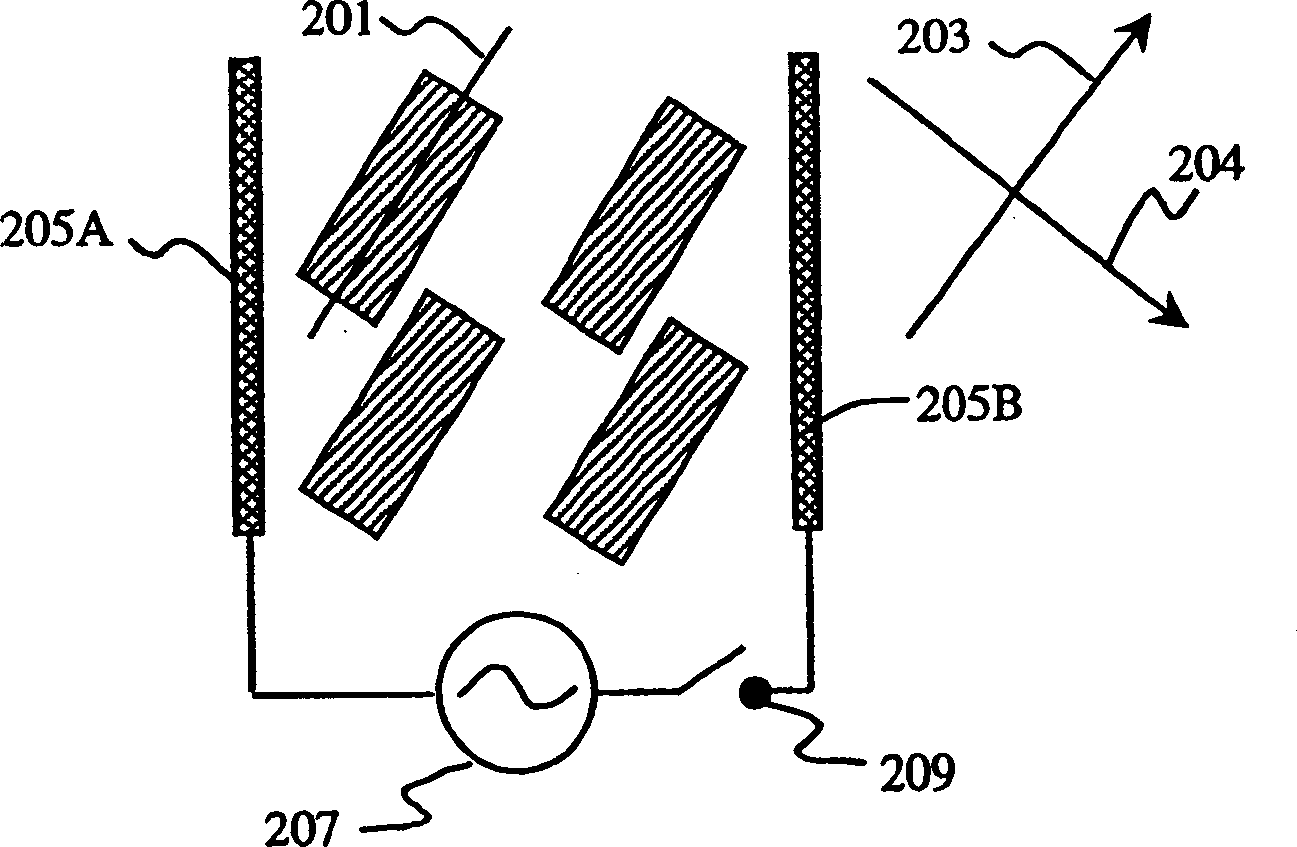
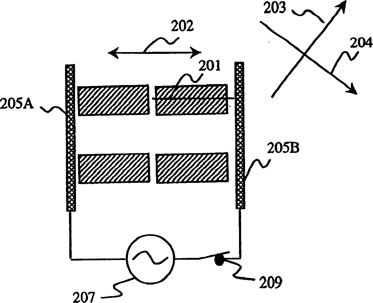
[0030] Figure 2A , 2B and 2C show the operation mode of the uniform type IPS mode liquid crystal display. exist Figure 2A In the OFF state shown, the liquid crystal optical axis 201 is parallel to the transmission axis of the first polarizer 203 . exist Figure 2B with 2C In the ON state shown, the liquid crystal optical axis 201 deviates from the direction of the transmission axis 203 of the polarizer. Figure 3A , 3B and 3C are corresponding to Figure 2A , 2B and a cross-sectional view of 2C. In the OFF state, light passing through the first polarizer 302 is not birefringent and is therefore absorbed by the second polarizer 303 . The OFF state thus gives the dark state. On the other hand, in the ON state, light exhi...


PUM

PropertyMeasurementUnit
hysteresis lossaaaaaaaaaa

Abstract

Disclosed is a display comprising an in-plane switching (IPS) mode liquid crystal cell, a polarizer, and a compensation film containing a positively birefringent material with the optic axis tilted in a plane perpendicular to the liquid crystal cell plane. Such displays exhibit an improved viewing angle characteristic.

Description

technical field [0001] The invention relates to a display comprising an in-plane switching nematic liquid crystal cell, a polarizer and a special compensation film. Background technique [0002] Liquid crystals (LCs) are widely used in electronic displays. In these display systems, the LC layer is usually located between a pair of polarizer layers. Incident light polarized by the first polarizer passes through the liquid crystal cell and is affected by the orientation of the molecules in the liquid crystal, which can be changed by applying a voltage across the cell. This altered light enters the second polarizer. Using this principle, the transmission of light incident from an external light source including ambient light can be controlled. The energy required to achieve this control is generally much less than the energy required for the luminescent materials used in other display types, such as cathode ray tubes. Accordingly, LC technology is used in a large number of ...

Claims


Application Information

Patent Timeline
Patent Type & Authority Applications(China)
IPC IPC(8): G02B5/30G02F1/1335G02F1/13363G02F1/1343
CPCG02F1/134363G02F1/133632G02F2413/105G02F1/1335
Inventor T·伊施卡瓦米向东
Owner NITTO DENKO CORP
Why Eureka
Try Eureka