Optical element, light guiding plate, backlight source and LCD device for synthetizing hologram by computer

A technology of optical elements and holograms, applied in the field of backlight, liquid crystal display devices, and light guide plates, can solve the problems of low manufacturing efficiency, complex structure, and high manufacturing cost, and achieve the effect of preventing interference fringes and high-quality optical elements

Inactive Publication Date: 2005-10-12
SUMITOMO CHEM CO LTD
View PDF4 Cites 12 Cited by
  • Summary
  • Abstract
  • Description
  • Claims
  • Application Information

AI Technical Summary

Problems solved by technology

[0003] In the aforementioned liquid crystal display device with the structure shown in FIG. 11 , since the structure of the brightness enhancing film and the prism sheet is used, there are problems that the structure is complex, the manufacturing efficiency is low, and the number of parts is large, and the manufacturing cost is high.
[0007] However, in the method for producing a hologram described in Patent Document 2 above, unnecessary interference fringes cannot be completely reduced.
In addition, in the method for producing a hologram described in Patent Document 2, the hologram is produced by setting conditions different from those of the actual use state (surrounding environment of the hologram) and making the imaging light incident to form interference fringes. For example, when the hologram is used as an optical element for a light guide plate, since the outgoing light is prone to non-uniformity (the in-plane distribution of the outgoing light and the non-uniform distribution of the outgoing angle), a lot of scattered light (into the unwanted direction) is generated. There is a lot of light emitted in the direction), and the light loss is large, so it is difficult to obtain a high-quality light guide plate with high diffraction efficiency

Method used


Image

  • Optical element, light guiding plate, backlight source and LCD device for synthetizing hologram by computer
  • Optical element, light guiding plate, backlight source and LCD device for synthetizing hologram by computer
  • Optical element, light guiding plate, backlight source and LCD device for synthetizing hologram by computer

Examples


Embodiment Construction

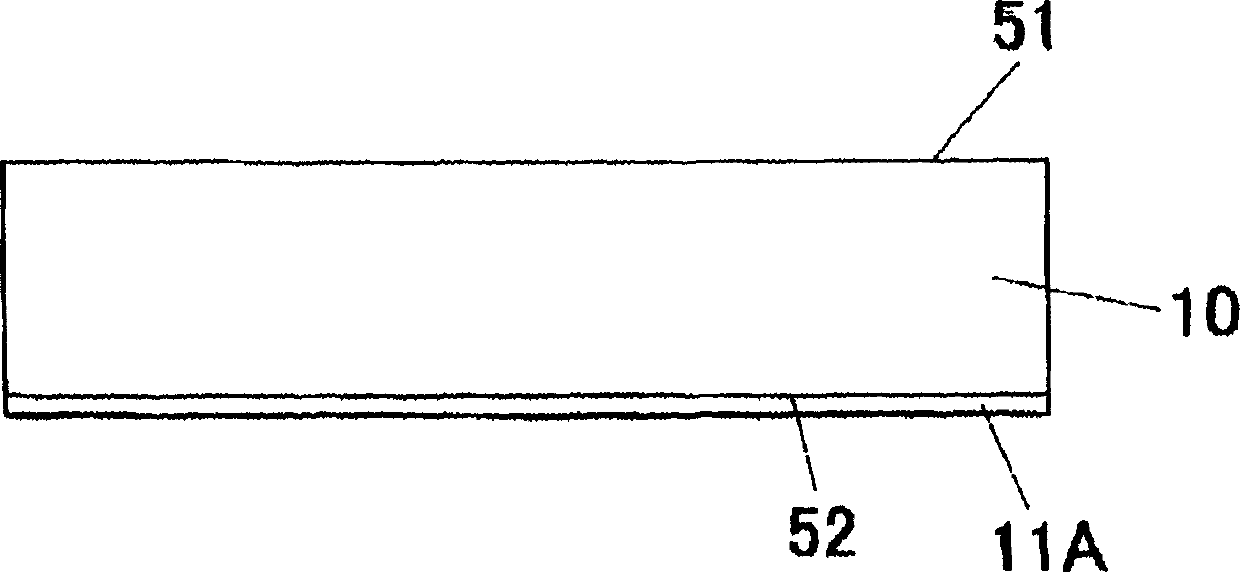
[0068] Fig. 1 shows an optical element-embodiment of the present invention. The optical element is used as a light guide plate, and is integrally formed by laminating a computer-synthesized hologram (11) on the bottom surface (52) of the light guide plate body (10), which is a translucent substrate. In this embodiment, a reflective computer-synthesized hologram (11A) is used as the computer-synthesized hologram. This hologram has a light diffraction function and a polarized light separation function.

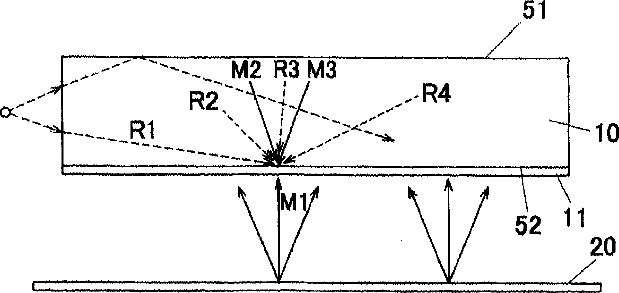
[0069] The aforementioned computer-synthesized hologram (11) is to reflect the actual use environment when the interference between the reference light and the object light arriving at each position of the hologram forming surface is calculated by a computer, as shown in Figure 3 As shown, assuming a state in which holograms are stacked on the bottom surface (52) of the aforementioned light guide plate body (10), the interference fringe data is obtained according to the calculat...


PUM

PropertyMeasurementUnit
refractive indexaaaaaaaaaa

Abstract

The optical element is provided with a computer composition hologram which is manufactured based on interference fringe data obtained by a computing method of individually computing the interference with reference to all the combination of a plurality of reference light R reaching the position and a plurality of object light M reaching the same position and summing up the interference data, in computing the interference generated by the reference light and the object light reaching every position on a hologram-formed surface by computer, on the other hand, computing the interference without taking the interference of the reference light R with the reference light R in the position into account.

Description

technical field [0001] The present invention relates to computer-synthesized holograms used in diffusion plates, polarized light separation elements, deflection elements, diffraction elements, and light-splitting elements, etc., light guide plates, backlight sources and liquid crystal display devices using the computer-synthesized holograms. Background technique [0002] It is well known as a liquid crystal display device to adopt the following structure, that is, a pair of polarizers (102) (103) are arranged on the upper and lower sides of the liquid crystal display device (101), and a backlight is arranged on the lower side of the lower polarizer (103). source. In many liquid crystal display devices such as notebook computers, an edge-light type backlight is used as the backlight in order to reduce thickness and realize low power consumption. As shown in Figure 11, the edge light type backlight generally adopts the method of introducing the light from the light source (11...

Claims


Application Information

Patent Timeline
Patent Type & Authority Applications(China)
IPC IPC(8): G02B5/32F21V8/00F21Y101/02F21Y103/00G02B5/02G02F1/1335G02F1/13357G03H1/08
CPCG02B6/2848G02F1/133524
Inventor 中塚木代春善甫康成窪田雅明
Owner SUMITOMO CHEM CO LTD
Why Eureka
Try Eureka