Rear-projection screen and optical device

A technology of optical devices and screens, applied in optics, projection devices, instruments, etc., can solve problems such as waste of light, inability to adjust the angle of light output, etc., and achieve the best visual quality effect

Inactive Publication Date: 2006-05-31
PRODISC TECH INC
View PDF0 Cites 2 Cited by
  • Summary
  • Abstract
  • Description
  • Claims
  • Application Information

AI Technical Summary

Problems solved by technology

Generally speaking, it is known that the columnar convex portions 121 of the known lenticular lens 12 are regularly arranged, and the height and curvature of the columnar convex portions 121 are substantially the same. The light emitting surface of the lens 12 is projected. Since the cylindrical convex portion 121 and the black stripes 122 are all regularly arranged, the light emitting angles of the light projected from the cylindrical lens 12 are roughly the same, and the light emitting angles of the light cannot be adjusted so that the light is concentrated. It is within the user's field of vision, thus causing a waste of light

Method used


Image

  • Rear-projection screen and optical device
  • Rear-projection screen and optical device
  • Rear-projection screen and optical device

Examples


Embodiment Construction

[0042] An optical device according to a preferred embodiment of the present invention will be described below with reference to related drawings.

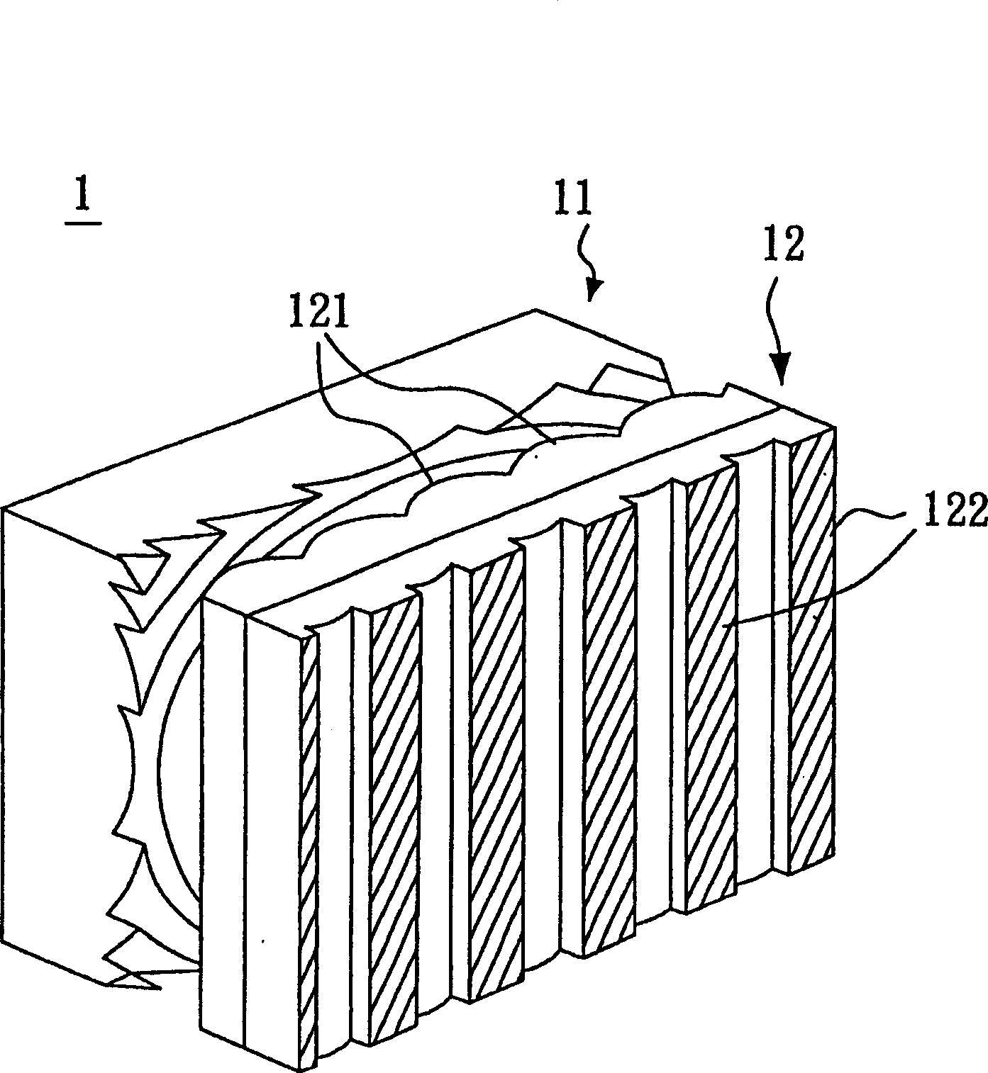
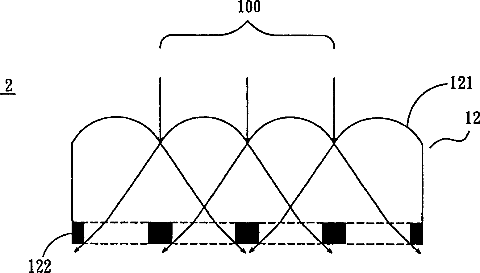
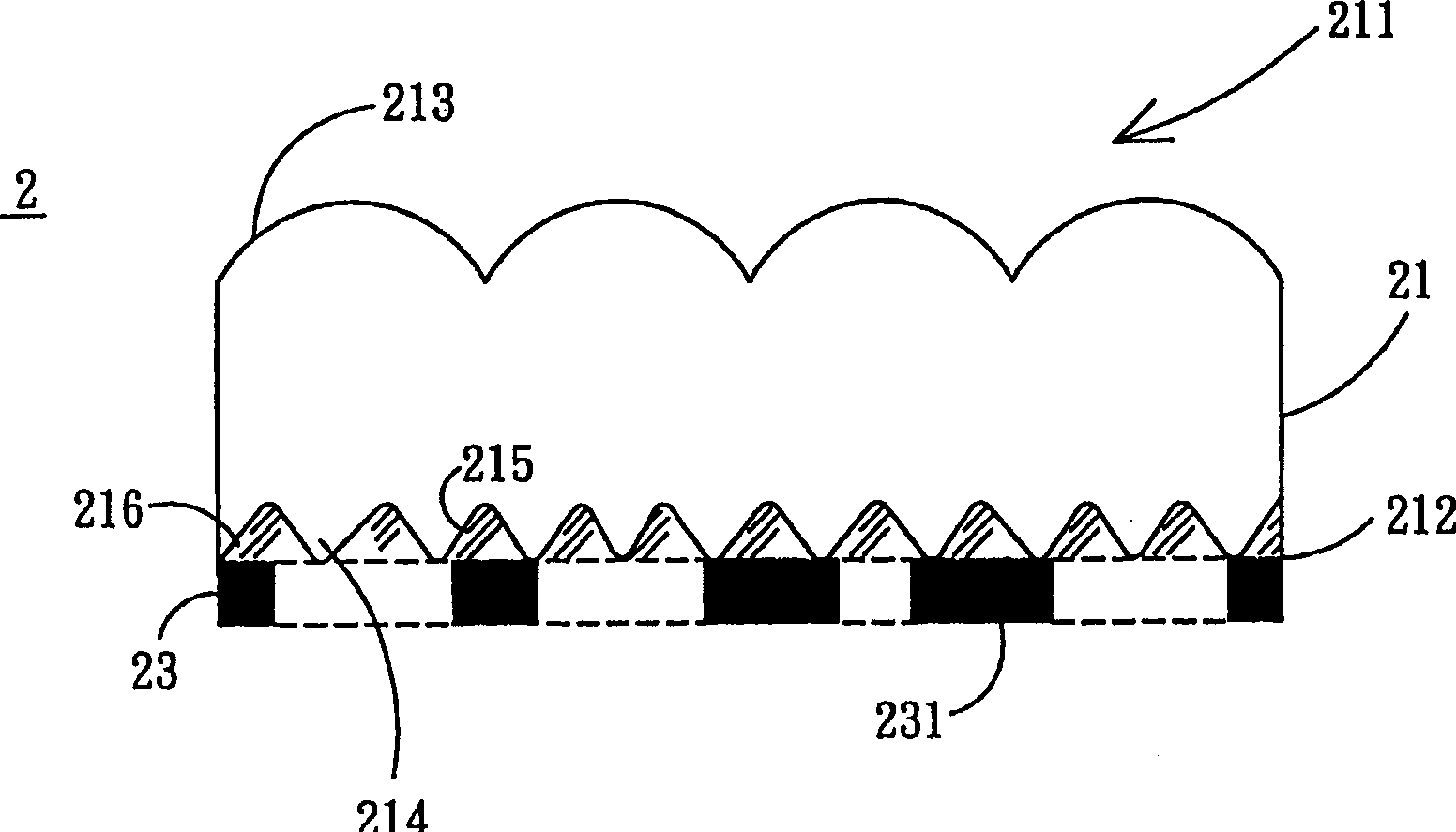
[0043] see Figure 2A Shown is a preferred embodiment of the optical device of the present invention. The optical device 2 includes an optical unit 21 and a light shielding layer 23 .

[0044] The optical unit 21 has a first surface 211 and a second surface 212 , and the first surface 211 is opposite to the second surface 212 . Wherein, the first surface 211 has a plurality of columnar protrusions 213 , and the second surface 212 has a plurality of irregular protrusions 214 . In addition, the protruding portion 214 has an inclined surface 215 , and each columnar convex portion 213 corresponds to at least one of the plurality of inclined surfaces 215 , so that the angle of the light passing through the inclined surface 215 is changed. In this preferred embodiment, the optical unit 21 is made of a light-transmitting material and i...


PUM


Abstract

A rear ¿C projection screen and its optical device consists of optical lens and optical device. It is featured as setting optical device opposite to optical lens and forming optical unit by optical unit with the first surface and the second surface as well as by irising layer with multiple light absorption units, setting said the first surface opposite to the second surface and adjoining irising layer to the second surface.

Description

technical field [0001] The present invention relates to a rear-projection screen and its optical device, in particular to a rear-projection screen and its optical device which can improve light utilization efficiency. Background technique [0002] In the past, rear projection televisions (Rear Projection Television) were mostly used for television teaching, as well as simulated real-scene training for pilots of airplanes and automobiles and locomotives. With the improvement of rear projection technology level, rear projection TV is also more and more favored by consumers. Rear-projection TVs feature large screens and clear images. Compared with CRT TVs, rear-projection TVs have the advantages of no radiation and large screen size, and can be directly connected to computers or other devices. Audio-visual equipment, to achieve the greatest entertainment effect. Therefore, the rear-projection television is gradually playing an important role in the entertainment display devic...

Claims


Application Information

Patent Timeline
Patent Type & Authority Applications(China)
IPC IPC(8): G03B21/602G03B21/625
Inventor 周彦均龚大焜
Owner PRODISC TECH INC
Why Eureka
Try Eureka