
Energy-saving LED warehouse lamp

An LED lamp bead and energy-saving technology, which is applied in the field of storage lights, can solve the problems of light shaking, small irradiation area, and low illumination, and achieve the effects of simplifying the structure, increasing the irradiation area, and increasing the illumination

Pending Publication Date: 2018-02-09
南通溢德行工业科技有限公司
View PDF0 Cites 1 Cited by
  • Summary
  • Abstract
  • Description
  • Claims
  • Application Information

AI Technical Summary

Problems solved by technology

[0003] However, the current LED factory warehouse lights are hung on the ceiling. Since the height of the ceiling is relatively high, and the light emitted by the LED factory warehouse lights is directed towards the surroundings, the light projected to the ground by the LED factory warehouse lights is relatively dark. It brings a lot of inconvenience to users, so someone designs another LED factory warehouse light to make up for this defect, that is, the LED factory warehouse light is suspended from the ceiling by a rope, so that the LED factory warehouse light is placed on the ceiling. The distance to the ground is shortened, so the light projected to the ground by the LED factory warehouse lights is brighter
However, there is also a big defect in this method. Since the LED factory warehouse lights are fixed to the ceiling by ropes, the LED factory warehouse lights are easy to swing due to external force, causing the LED factory warehouse lights to sway. There is obvious shaking of the light. The most important point is that the existing LED factory warehouse lights are in the form of direct irradiation, and the irradiation area is relatively small, the power consumption is large, and the illumination is low.

Method used


Image

  • Energy-saving LED warehouse lamp
  • Energy-saving LED warehouse lamp

Examples


Embodiment Construction

[0013] The technical solutions of the embodiments of the present invention will be clearly and completely described below in conjunction with the accompanying drawings of the present invention.

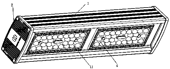
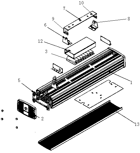
[0014] Such as Figure 1~2 As shown, an energy-saving LED storage light disclosed by the present invention includes a lamp body 1 , end covers 2 on both sides, a mounting bracket, a light source board, a driving power supply, an emergency power supply 3 and a lens 4 .

[0015] Specifically, the lamp body 1 is a cavity structure, and the two ends are sealed and fixed through the end cover 2 and the waterproof sealing ring 5. The bottom surface of the lamp body 1 has a plurality of light source openings (not shown in the figure), and the light source board is installed on the In the cavity of the lamp body, and the installation position corresponds to the light source opening, a plurality of LED lamp beads are distributed on the light source board, and when the light source board is ins...


PUM


Abstract

The invention discloses an energy-saving LED warehouse lamp. The energy-saving LED warehouse lamp comprises a lamp body, end covers on the two sides, an installation bracket, a light source plate, a driving power source and lenses, wherein the lamp body is of a cavity structure, and the bottom face of the lamp body is provided with a plurality of light source openings; the light source plate is installed in a cavity of the lamp body and aligned to the light source openings, and thus, LED lamp beads on the light source plate can illuminate downwards; the driving power source is installed in thecavity of the lamp body and connected with the light source plate so that the light source plate can be driven to work, and an input wire of the driving power source penetrates through the upper endface of the lamp body to be connected with a mains supply; the end covers are fixed to the two sides of the lamp body through cooperation of screws and water-proof sealing rings; the upper end face ofthe lamp body is fixed to the top of a warehouse through the installation bracket; and the lenses are fixed to the light source openings of the lamp body from the outer side, so that the LED lamp beads are covered inside the lenses, and light refraction is formed.

Description

technical field [0001] The invention relates to a storage lamp, in particular to an energy-saving LED storage lamp. Background technique [0002] Based on the characteristics of power saving and long service life, and the luminous brightness is stronger than ordinary incandescent lamps, LEDs are currently widely used in lighting, and it is also a major trend in the future. [0003] However, the current LED factory warehouse lights are hung on the ceiling. Since the height of the ceiling is relatively high, and the light emitted by the LED factory warehouse lights is directed towards the surroundings, the light projected to the ground by the LED factory warehouse lights is relatively dark. It brings a lot of inconvenience to users, so someone designs another LED factory warehouse light to make up for this defect, that is, the LED factory warehouse light is suspended from the ceiling by a rope, so that the LED factory warehouse light is placed on the ceiling. The distance to ...

Claims


Application Information

Patent Timeline
IPC IPC(8): F21S9/02F21V23/00F21V5/04F21V5/08F21V21/104F21Y115/10
CPCF21S9/02F21V5/048F21V5/08F21V21/104F21V23/02F21Y2115/10
Inventor 何元武刘玉芳
Owner 南通溢德行工业科技有限公司
Learn More