
Cooking vessel
A technology of cooking containers and containers, which is applied in the direction of cooking utensils, cooking utensil supports, cooking utensil covers, etc., can solve the problems of blocking and hindering the passage of food, and achieve the effect of simple technology
- Summary
- Abstract
- Description
- Claims
- Application Information
AI Technical Summary
Problems solved by technology
Method used
Image

Examples
Embodiment Construction
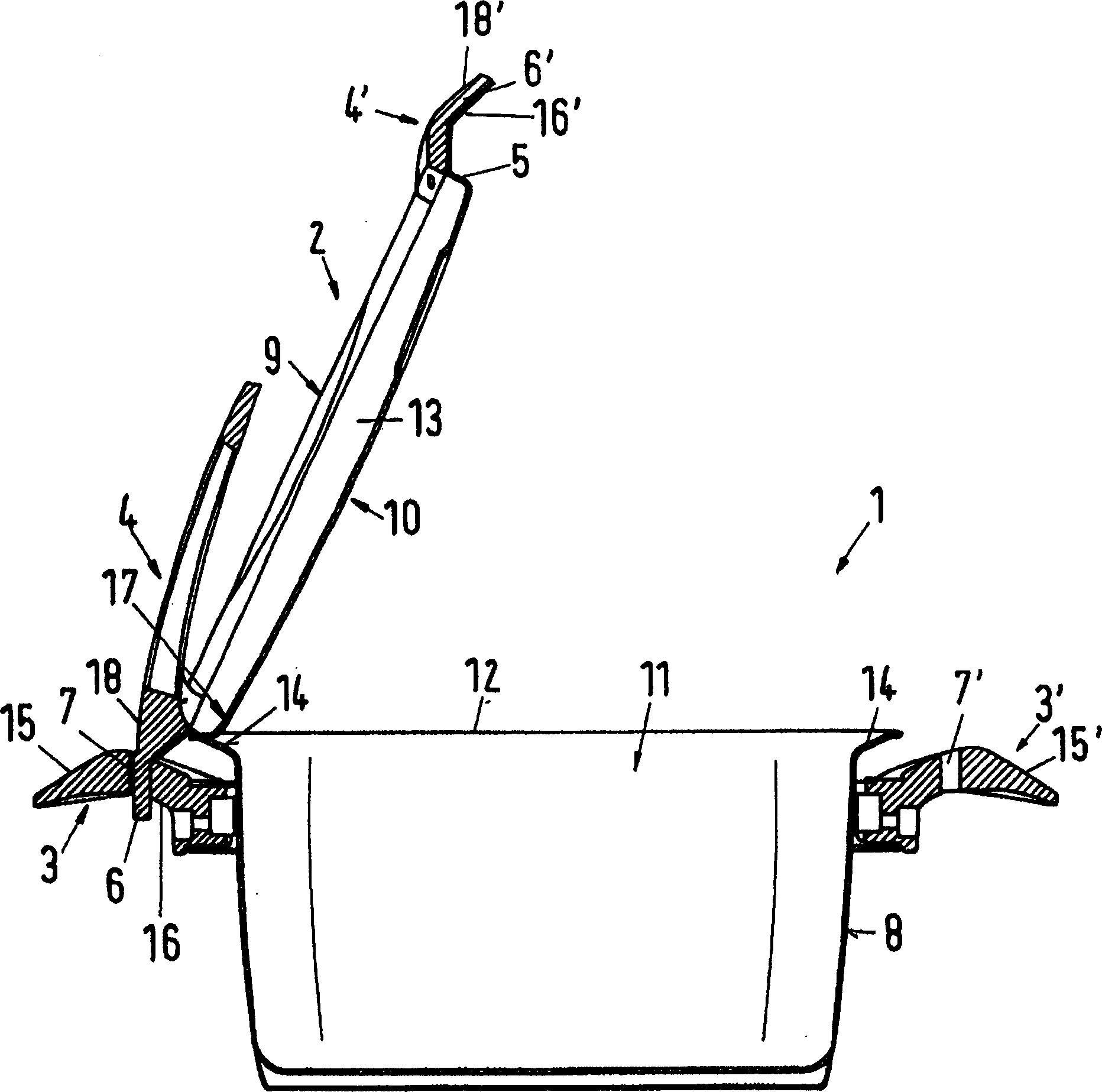
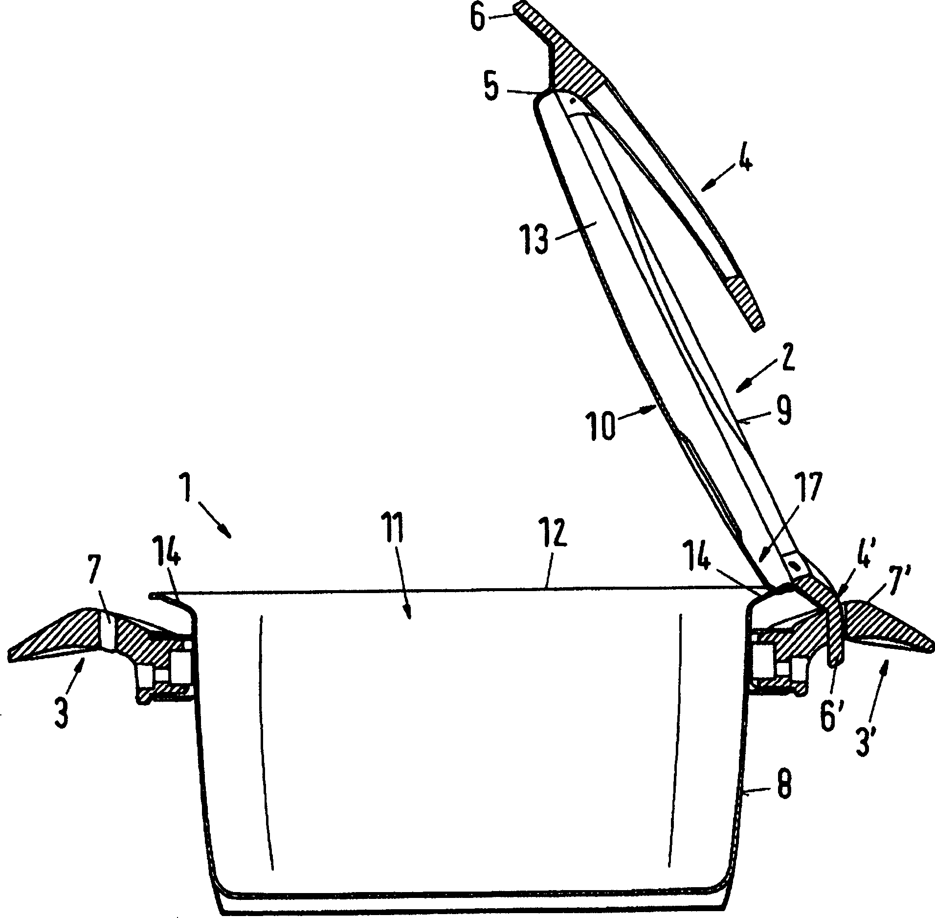
[0025] figure 1 The cooking vessel shown in includes a vessel 1 and a lid 2 . The container 1 has two identical container handles 3, 3', one (in this illustration) to the left of the peripheral wall 8 and one to the right of the peripheral wall 8. The cover 2 has two cover handles 4, 4' in corresponding positions. The two lid handles 4, 4' respectively have a handle locking section 6, 6' protruding radially outward beyond the lid edge 5, and the handle locking sections can be inserted into the respective holes of the corresponding container handles 3, 3' in this way. 7, 7', so that the lid 2 is held on the container 1 in an upright position in which at least the lowermost area of the inner side 10 of the lid is located above the container opening 11, because the container handles 3, 3' and the upper The container rim 12 of the container 1 rests at a correspondingly small distance on the peripheral wall 8 of the container 1 , and the handle locking sections 6 , 6 ...
PUM
 Abstract
Description
Claims
Application Information