Projecting unit, and method for adjusting brightness of light source

A projection device and brightness technology, applied in projection devices, optics, optical components, etc., can solve problems such as affecting the quality of 170 images on the screen

Inactive Publication Date: 2007-02-21
BENQ CORP
View PDF0 Cites 19 Cited by
  • Summary
  • Abstract
  • Description
  • Claims
  • Application Information

AI Technical Summary

Problems solved by technology

[0004] However, whether the brightness of the traditional projection device 100 is strong or not depends on the light L generated by the light source module 110. When the light so

Method used


Image

  • Projecting unit, and method for adjusting brightness of light source
  • Projecting unit, and method for adjusting brightness of light source
  • Projecting unit, and method for adjusting brightness of light source

Examples


Embodiment Construction

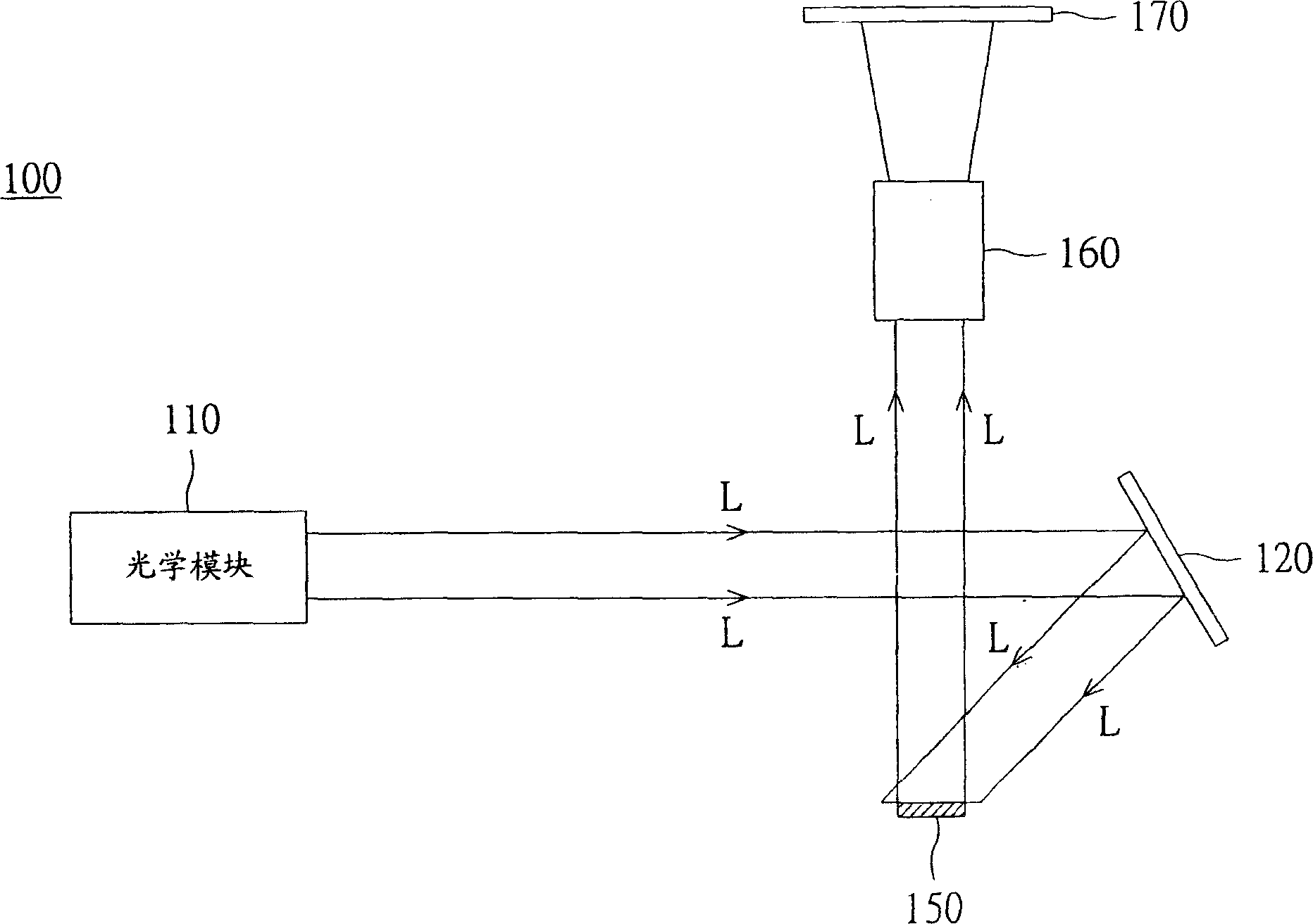
[0013] The projection device utilizes the light source module to generate the required brightness of the light source. The light source module includes a light bulb and an electronic ballast (Ballast). The electronic ballast drives the light bulb to produce light with the required brightness. When the light bulb decays and ages (Decay), the brightness of the projection device will decrease accordingly. Therefore, when the brightness of the light source decreases with the decay and aging of the bulb, if the projection device can control the output power of the electronic ballast according to the change of the brightness of the light source to keep the projection device working at an ideal brightness, the projection device will have better image performance. .

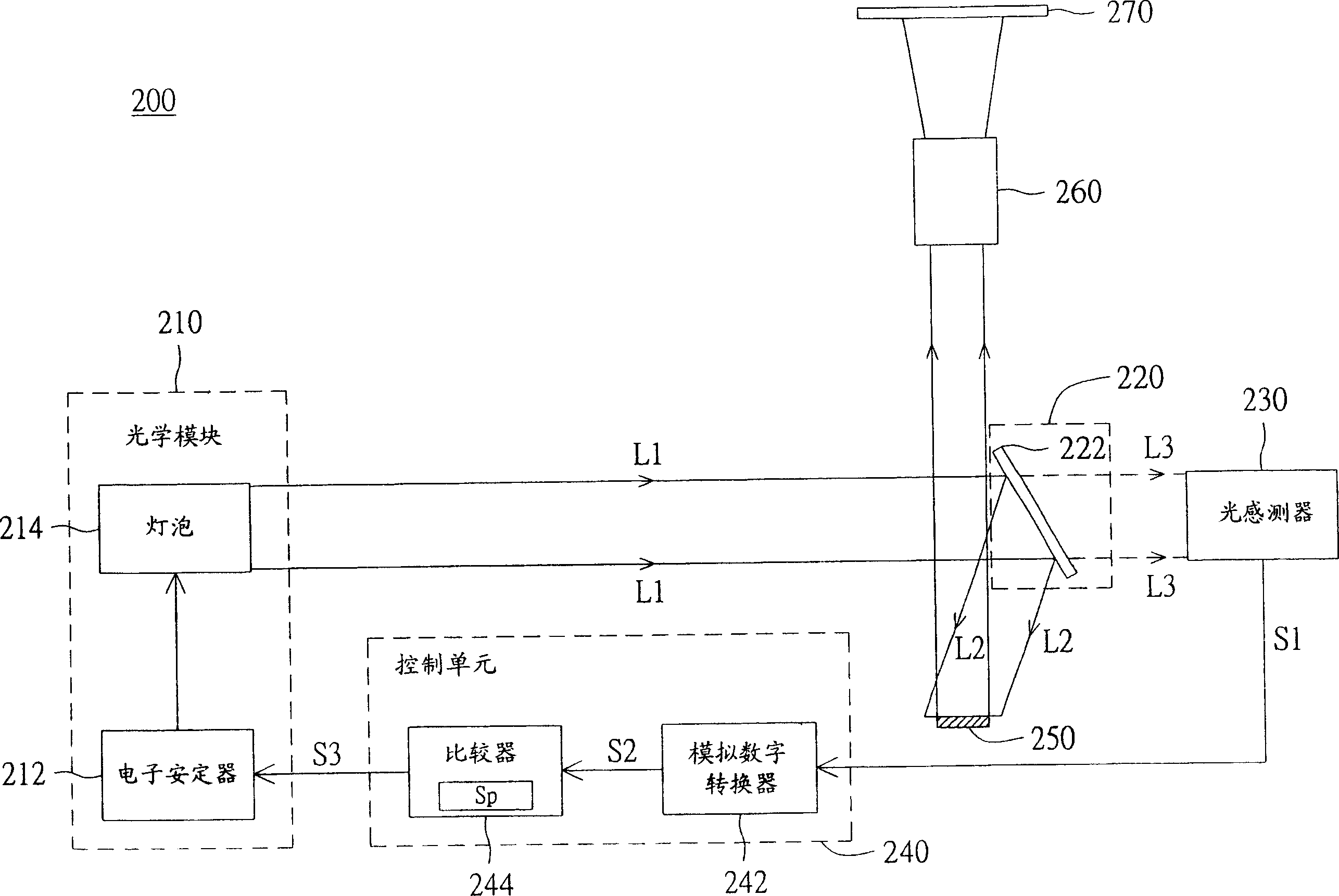
[0014] Please refer to figure 2 , which shows a schematic diagram of a projection device capable of automatically adjusting brightness according to a preferred embodiment of the present invention. The projection devic...


PUM


Abstract

A projection device consists of light source module used to generate the first light beam, reflection module for receiving the first light beam and for reflecting the first light beam to be the second one as well as for forming the third one by passing partial light of the first reflection light beam through reflection module, projecting the second one to form an image by imaging module, sensing brightness of the third one by light transducer in order to output a sensing signal, outputting a control signal according to said sensing signal and controlling light source module to make the first light beam retain on a fixed brightness by control unit.

Description

technical field [0001] The invention relates to a projection device, in particular to a projection device capable of automatically adjusting the brightness of a light source. Background technique [0002] In this increasingly ubiquitous environment, projectors play an indispensable role, whether in a meeting presentation in the office or in a personal home theater. Therefore, how to improve the quality of the projector has become an increasingly important issue. [0003] Please refer to figure 1 , which is a schematic diagram of a conventional projection device. The traditional projection device 100 includes a light source module 110 , a reflection module 120 , an image module 150 and an imaging module 160 . The light source module 100 is used to generate a light L, and the light source module 110 uses a light bulb (Lamp) to emit light, for example. The light L is reflected to the image module 150 by the reflection module 120 , the reflection module 120 is, for example, ...

Claims


Application Information

Patent Timeline
IPC IPC(8): G02B27/18G03B21/00H04N9/64
Inventor 詹淞玮
Owner BENQ CORP
Why Eureka
Try Eureka