LED control circuit

A technology of control circuit and control unit, applied in the direction of electrical components, etc., can solve the problems of poor constant current and constant voltage effect, inability to adjust the dimming of LED groups with different color temperatures, etc. easy-to-achieve effects

Pending Publication Date: 2020-05-15
上海兴为视觉科技股份有限公司
View PDF7 Cites 1 Cited by
  • Summary
  • Abstract
  • Description
  • Claims
  • Application Information

AI Technical Summary

Problems solved by technology

[0004] The technical problem to be solved by the present invention is to provide an LED control circuit in order to overcome the disadvantage that the LED control circuit in the prior art has poor constant current and constant voltage effect and cannot realize dimming and color adjustment for LED groups with different color temperatures.

Method used


Image

  • LED control circuit
  • LED control circuit
  • LED control circuit

Examples


Embodiment 1

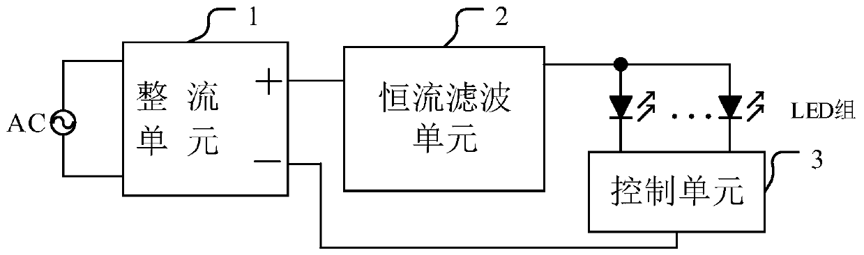
[0030] This embodiment provides an LED control circuit, such as figure 1 As shown, the LED control circuit includes a rectifying unit 1, a constant current filtering unit 2, a control unit 3 and several LED groups, and these LED groups have different color temperatures.

[0031] The two input ends of the rectification unit 1 are respectively connected to the two ends of the AC mains, the constant current filter unit 2 is electrically connected to the positive output end of the rectification unit 1, and the output end of the constant current filter unit 2 is electrically connected to several LED groups, Several LED groups are electrically connected with the control unit 3 .

[0032] The rectifier unit 1 rectifies the AC mains and outputs the DC signal to the constant current filter unit 2. The constant current filter unit 2 converts the DC signal into a constant current and constant voltage signal and outputs it to several LED groups to provide constant current and constant vol...

Embodiment 2

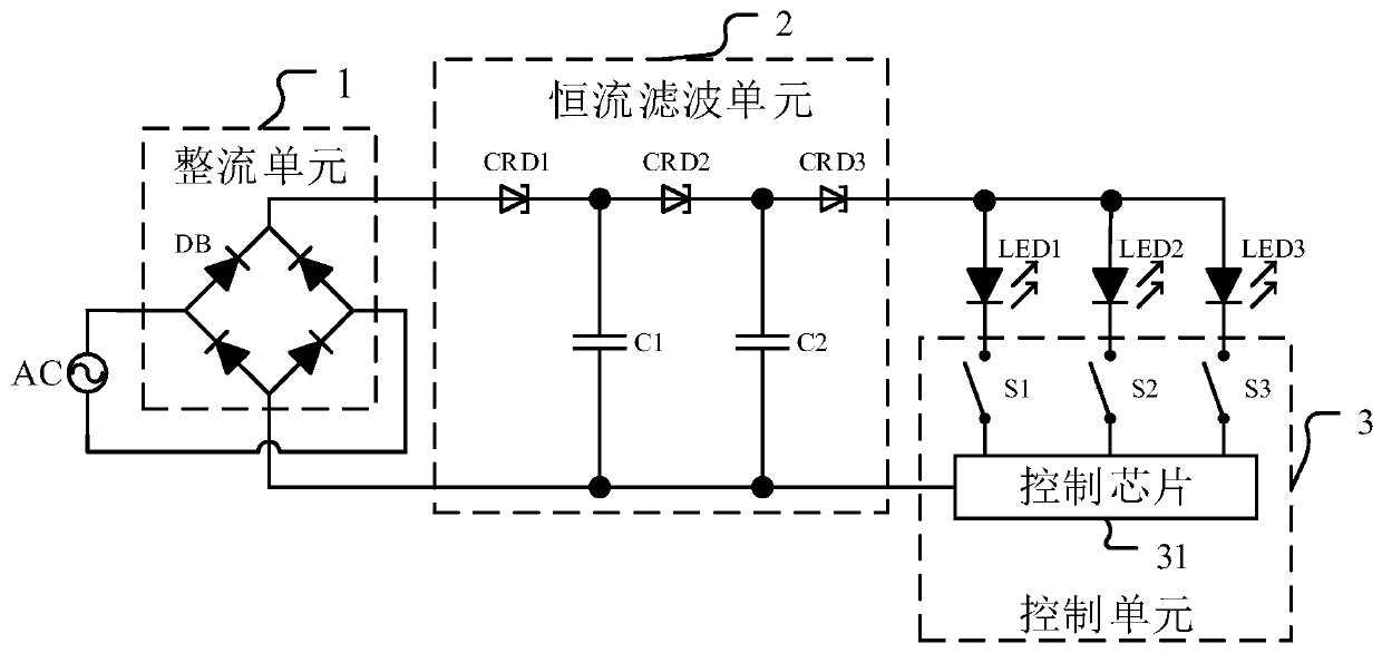
[0036] This embodiment is a further refinement of Embodiment 1, such as figure 2 As shown, the rectifier unit 1 of the LED control circuit includes a bridge rectifier unit DB; the constant current filter unit 2 includes a first constant current diode CRD1, a second constant current diode CRD2, a third constant current diode CRD3, a first capacitor C1 and The second capacitor C2; the control unit 3 includes a control chip 31 and several switches corresponding to the LED groups one by one.

[0037] Several are any number greater than or equal to 2, here it is assumed to be 3, that is, this embodiment includes 3 LED groups: the first LED group LED1, the second LED group LED2 and the third LED group LED3, assuming that among them The first LED group LED1 is turned on to emit red light, the second LED group LED2 is turned on to emit green light, and the third LED group LED3 is turned on to emit blue light.

[0038] The bridge rectifier unit DB includes 4 diodes, which perform ful...

Embodiment 3

[0051] This embodiment is a further optimization on the basis of embodiment 1 or 2, as Figure 4 As shown, the LED drive circuit also includes a protection circuit 4 for reducing the current and voltage of the AC mains. The rectification unit 1 , constant current filter unit 2 and control unit 3 in this embodiment are all the same as those in Embodiment 2, and will not be repeated here.

[0052] The protection unit 4 includes a third capacitor C3 and a first resistor R1 connected in parallel, one end of the third capacitor C3 is electrically connected to one end of the first resistor R1, and the input end of the protection unit 4 is electrically connected to one end of the AC mains. The other end of the third capacitor C3 is electrically connected to the other end of the first resistor R1 , and is used as an output end of the protection unit 4 to be electrically connected to an input end of the rectification unit 1 .


PUM


Abstract

The invention discloses an LED control circuit. The LED control circuit comprises a rectification unit, a constant-current filtering unit, a control unit and a plurality of LED groups, and the LED groups have different color temperatures; two input ends of the rectification unit are respectively connected to two ends of an alternating current mains supply, and the rectification unit outputs a direct current signal; the constant-current filtering unit is electrically connected with the positive output end of the rectification unit, the output end of the constant-current filtering unit is electrically connected with the plurality of LED groups, and constant-current and constant-voltage electric signals are output to each LED group; the plurality of LED groups are electrically connected withthe control unit; and the control unit controls the conduction or cut-off of each LED group. According to the invention, the alternating-current mains supply is connected with the LED groups with different color temperatures after passing through the rectification unit and the constant-current filtering unit, so that a better constant-current and constant-voltage effect can be realized, and the brightness and the light-emitting stability of the LED are effectively improved; and the brightness of each LED group is effectively controlled through the control chip, so that the dimming and color adjusting functions are realized. The circuit is simple in structure, low in cost and easy to implement.

Description

technical field [0001] The invention relates to the field of LED (light emitting diode) lighting, in particular to an LED control circuit. Background technique [0002] In the field of lighting technology, LEDs have the advantages of high luminous efficiency, energy saving, and long life, and are widely used in various lighting fixtures. Since the LED must be started and working normally under the appropriate current and voltage, the LED generally needs to be matched with the driving power supply before it can be connected to the mains. The LED control circuit acts as a converter to convert the power supply into a specific voltage and current to control and drive the LED to emit light. LEDs with different color temperatures emit different colors of light, and the brightness of LEDs with each color temperature can be adjusted separately to achieve dimming and color adjustment applications for LED combinations. For example, combining red, green and blue LEDs together and adjus...

Claims


Application Information

Patent Timeline
Patent Type & Authority Applications(China)
IPC IPC(8): H05B45/34H05B45/20H05B45/10
Inventor 苏贞张恒郑凯何国兴
Owner 上海兴为视觉科技股份有限公司
Why Eureka
Try Eureka