Method for mounting plastic electric machine casing and bearing device

A technology for bearing devices and motor housings, which is applied in the direction of electromechanical devices, manufacturing motor generators, electrical components, etc., can solve problems such as increased noise, difficulty in meeting the requirements for installation coaxiality, and poor operating effects, so as to reduce mechanical The effect of vibration and noise, superior matching adjustment performance, and high positioning accuracy of the rotating shaft

A technology for bearing devices and motor housings, which is applied in the direction of electromechanical devices, manufacturing motor generators, electrical components, etc., can solve problems such as increased noise, difficulty in meeting the requirements for installation coaxiality, and poor operating effects, so as to reduce mechanical The effect of vibration and noise, superior matching adjustment performance, and high positioning accuracy of the rotating shaft

CN1949632AInactive Publication Date: 2007-04-18η½—δΈ–ζ˜Ž

Image

  • Method for mounting plastic electric machine casing and bearing device
  • Method for mounting plastic electric machine casing and bearing device
  • Method for mounting plastic electric machine casing and bearing device

Examples


Embodiment Construction

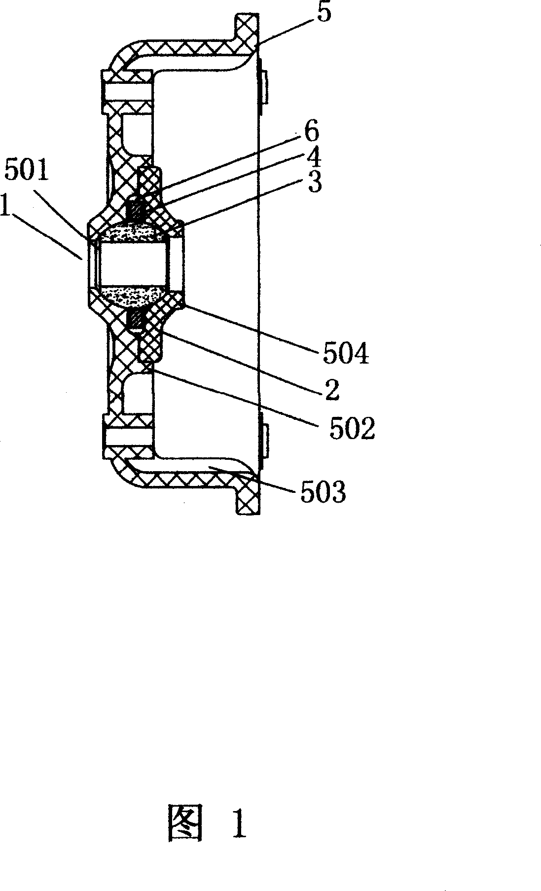
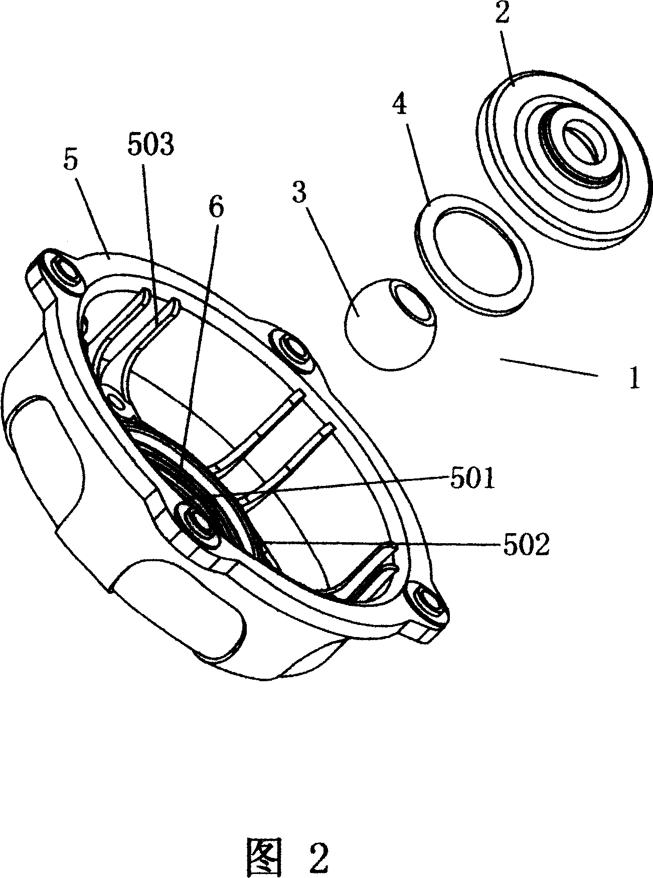
[0024] As shown in Figures 1 and 2, the installation method of the plastic motor housing and the bearing device, the bearing device 1 includes a gland 2, an oil-impregnated bearing 3 and an oil-soaked felt 4, and is characterized in that it includes the following installation steps:

[0025] 1), first use the injection molding method to be injection-molded into the motor plastic housing 5 with the bearing chamber cavity 501, for subsequent use;

[0026] II) Install the oil-impregnated bearing 3 and the oil-impregnated felt 4 into the bearing chamber cavity 501 of the above-mentioned plastic shell 5, then fix the gland 2 on the bearing chamber cavity 501, and fix the oil-impregnated bearing 3 and the oil-impregnated felt 4 in the bearing chamber cavity 501 inside.

[0027] The gland 2 is a plastic gland 2, and the plastic gland 2 is welded or fastened on the bearing chamber 501 of the plastic shell 5 by ultrasonic welding.

[0028] The bearing chamber 501 of the plastic housin...


PUM


Abstract

The invention discloses a plastic motor case and bearing device installing method, where the bearing device comprises gland, oil containing bearing and oiled felt, and the method comprises the steps of: 1) firstly injection-moulding a plastic motor case with bearing cavity for reserving; and II) placing the oil-containing bearing and oiled felt in the bearing cavity, and then fixing the gland on the bearing room to fix them in the bearing cavity. And it has advantages of simple process, low manufacturing cost, coaxial matching, low operating heat and long service life.

Description

technical field [0001] The invention relates to a method for installing a plastic motor casing and a bearing device. Background technique [0002] In the prior art, the installation method of the motor casing and the bearing device is quite different according to the different materials, such as: 1), the motor casing adopts iron plate and is stretched and formed, and aluminum alloy or cast iron material is selected , after casting and machining; the motor housing made of the above metal materials has the following disadvantages when assembled with the bearing device: first, the metal housing has complicated processing technology, many processes and low yield, The product stability is poor, and the processing cost is high; moreover, the metal material pollutes the environment greatly, which is not conducive to environmental protection. 2) The motor shell is made by traditional injection molding process. The bearing is embedded in the mold and the shell is injection molded at...

Claims


Application Information

Patent Timeline
18 Apr 2007
Publication
CN1949632A
IPC
H02K15/00; H02K15/14
Inventors
η½—δΈ–ζ˜Ž