

Electric dust collector
A kind of equipment and electric technology, which is applied in the direction of mining equipment, dust prevention, electrode structure, etc., can solve the problem of large particle size dust particles reducing the dust collection rate, etc.
- Summary
- Abstract
- Description
- Claims
- Application Information
AI Technical Summary
Problems solved by technology
Method used
Image

Examples
no. 1 example
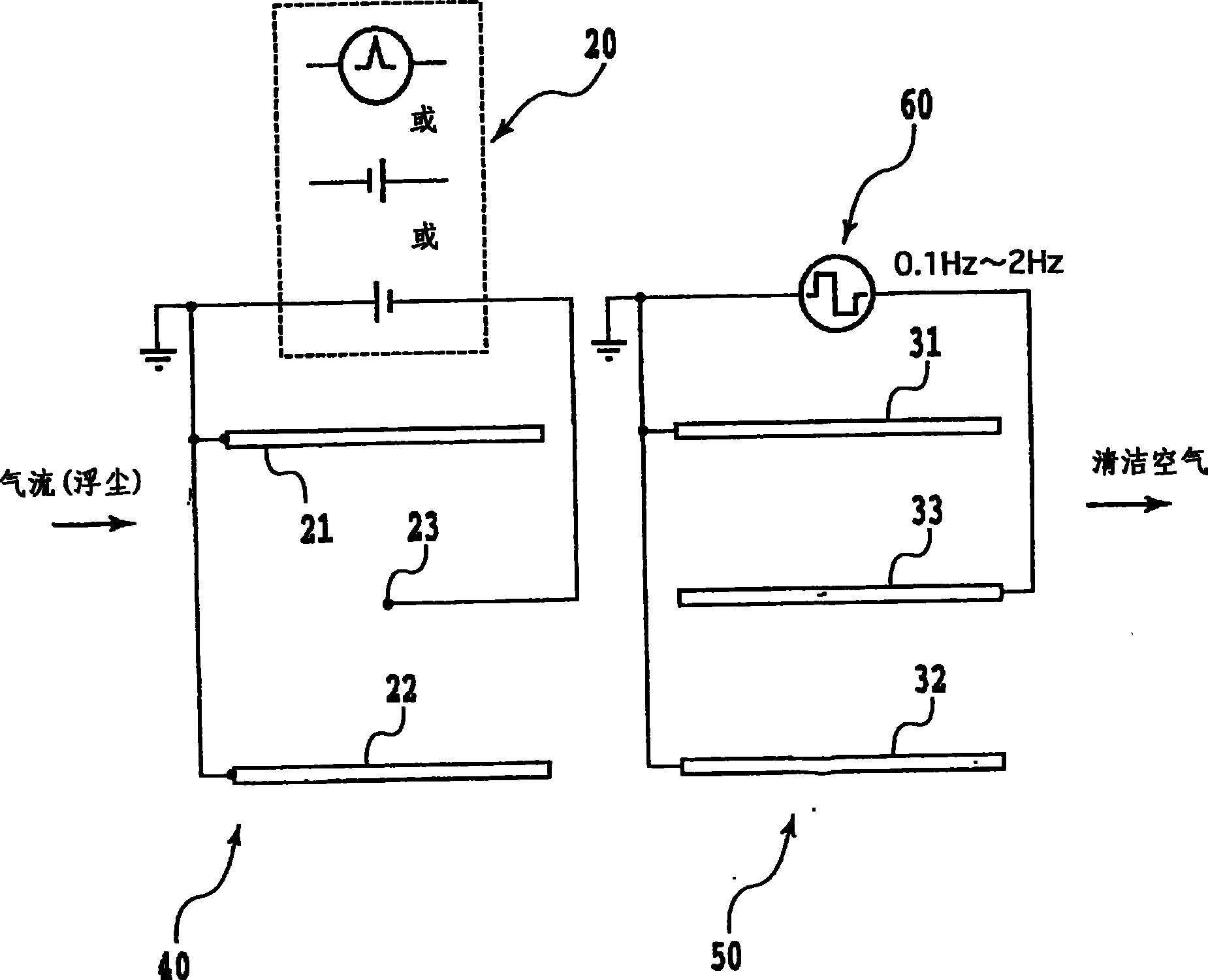
[0044] Fig. 1 is a cross-sectional structure of an electric dust collector according to a first embodiment of the present invention.
[0045] This electric vacuum cleaner includes a charging unit 40 and a dust collection unit 50 . The charging part 40 has a straight-to-plate electrode structure, including a pair of ground electrodes 21 and 22 and a straight high-voltage electrode 23 . The high voltage power supply 20 applies a DC high voltage between the ground electrodes 21 and 22 and the high voltage 23 to generate corona discharge in the charging unit 40 . The polarity of DC high voltage is either positive or negative, and the voltage can be pulse voltage.
[0046] The suction part 50 has a parallel plate electrode structure, including ground electrodes 31 and 32 as a pair of plates and a high voltage electrode 33 as a plate. The AC high voltage power supply 60 applies AC high voltage (with a frequency of 0.1-2 Hz) between the ground electrodes 31 and 32 and the high volt...
no. 2 example
[0060] It can be speculated that in the rectangular voltage waveform, the greater the voltage change rate dv / dt corresponding to the voltage gradient in section B in Figure 3, the more it can limit redispersion and maintain a higher dust collection rate. But the problem is that the higher the voltage change rate dv / dt, the more the induced current value increases, so it is required to increase the current resistance of a certain part inside the high-voltage power supply equipment, and for the same reason, it is also proposed to increase the cable size. thick question. This becomes an important practical issue when selecting the optimum dv / dt value for the rate of voltage change.
[0061] In this regard, an electric vacuum cleaner according to a second embodiment of the present invention will be described below, which achieves a high vacuum rate and has a necessary minimum voltage change rate dv / dt value when using a rectangular waveform AC high voltage, It also simplifies pow...
no. 3 example
[0101] Fig. 16 shows an electric vacuum cleaner according to a third embodiment of the present invention.
[0102] The electrode structures of the charging part 40 and the dust collecting part 50 are similar to those in FIG. 1 , so they will not be described in detail.
[0103] In the case of FIG. 16, the voltage applied to the charging section 40 consists of AC high voltage (ie, sinusoidal or rectangular AC high voltage).
[0104] AC high voltage is applied between the linear motor 23 and the plate electrodes 21 and 22 of the charging part 40 . As the AC high voltage, not only a sinusoidal AC high voltage but also a rectangular AC high voltage can be used. Therefore, according to this example, the output waveform of the AC high-voltage power supply 80 can be arbitrarily selected. Similarly, for the output waveform of the AC high voltage power supply 90 of the dust collection part 50, not only a sinusoidal AC high voltage but also a rectangular AC high voltage can be selecte...
PUM
 Abstract
Description
Claims
Application Information