Antitheft lock for use in well cover

An anti-theft lock and manhole cover technology, which is applied in the field of anti-theft locks, can solve the problems of insufficient strength of non-ferrous manhole covers, high cost of cement manhole covers, and manhole covers can only be eliminated, and achieve the effect of simple structure, flexible mechanism and few mechanical nodes

An anti-theft lock and manhole cover technology, which is applied in the field of anti-theft locks, can solve the problems of insufficient strength of non-ferrous manhole covers, high cost of cement manhole covers, and manhole covers can only be eliminated, and achieve the effect of simple structure, flexible mechanism and few mechanical nodes

CN1966871AInactive Publication Date: 2007-05-23θƒ‘ζŒ―εŽ

Image

  • Antitheft lock for use in well cover
  • Antitheft lock for use in well cover
  • Antitheft lock for use in well cover

Examples


Embodiment Construction

[0030] The structure of the present invention will be further described below in conjunction with the embodiments by the accompanying drawings:

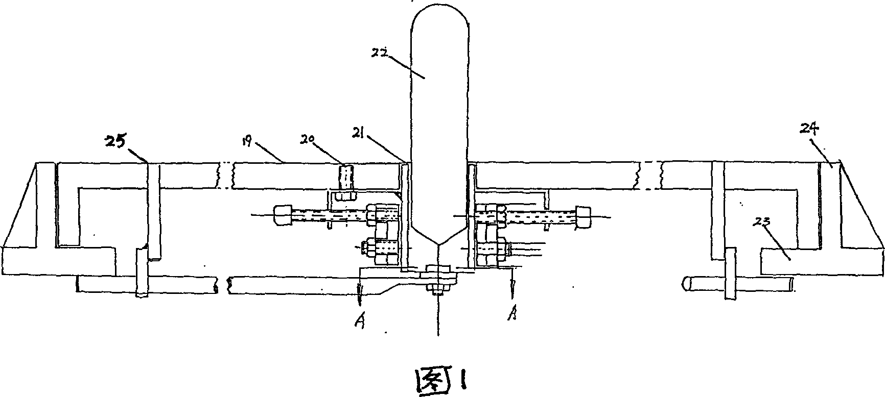
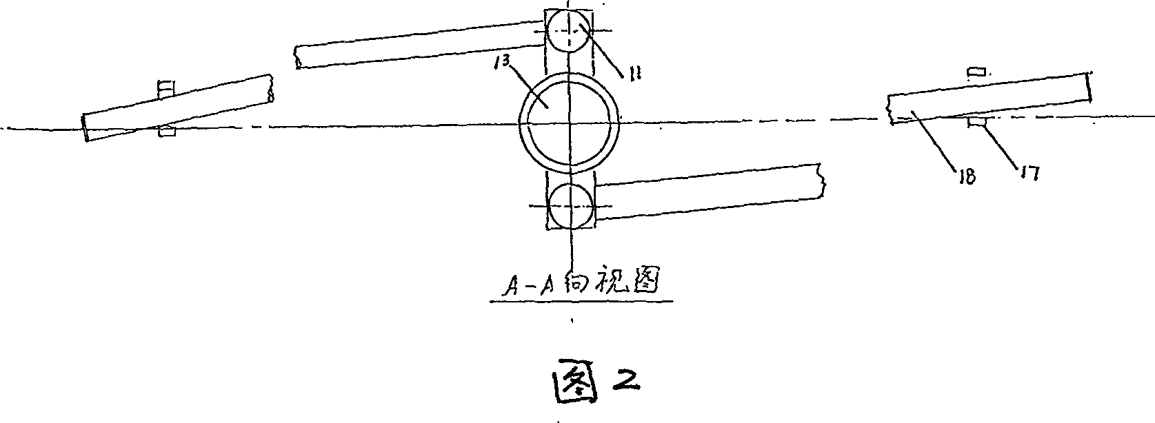
[0031] The anti-theft lock used on the well cover of the present invention, as shown in Figures 1, 2, and 4, has three parts: a key, a lock cylinder mechanism, and a tongue;

[0032] Wherein, the key 22 can itself be the key core 1, that is, the whole body is a bar-shaped rare earth permanent magnet block, such as: neodymium iron stilbium, or neodymium nickel cobalt, or permanent magnetic ferrite;

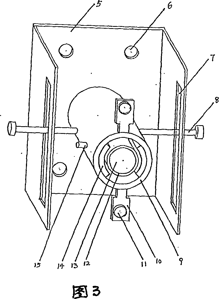
[0033] As shown in Figures 5 and 6, it is also possible that only the key core 1 part of the key 22 is a bar-shaped rare earth permanent magnet block, that is, the key 22 is made up of the key core 1, the magnetic handle 2 and the fixed bar 4; the key core 1 It is a special-shaped cylinder with a grooved waist-shaped cross section (as shown in Figure 6), made of permanent magnetic materials, which include various rare earth permanent magn...


PUM


Abstract

An antitheft lock on the well cover comprises key, lock pin and tongue, with the lock pin fastened on the lower surface of the well cover, the key going to the lock hole through the hole on the well cover, and the tongue, under the control of the key, connected to the lock pin. It solves the theft issue of the well cover with low cost, safety. It can also be used to modify the existing well covers.

Description

Technical field [0001] The invention discloses an anti-theft lock for well covers, which is used on various well covers on the road surface and belongs to the field of anti-theft devices for the well covers on the road surface. Background of the invention [0002] There are a large number of underground buildings in municipal engineering, which are used to lay power cables, communication cables and optical cables, water supply pipelines and accessories, reclaimed water pipelines and accessories, heating pipelines and accessories, oil pipelines and accessories, etc. These underground buildings need to be equipped with ground exits at certain distances for engineering construction and maintenance personnel to enter and exit. Manhole covers are required for each exit to protect the safety of underground facilities and the safety of pedestrians and vehicles on the ground. Manhole covers are widely distributed in urban areas. High streets and alleys as well as suburbs and country...

Claims


Application Information

Patent Timeline
23 May 2007
Publication
CN1966871A
IPC
E02D29/14
Inventors
θƒ‘ζŒ―εŽ