Check patentability & draft patents in minutes with Patsnap Eureka AI!

Systems and methods for determining fuse loads for fuses having multiple loads from multiple sub-models

a technology of fuses and sub-models, applied in the field of systems and methods for identifying loads on fuses of vehicles, can solve the problems of increasing the complexity of designing power systems to provide power to electronic devices, increasing the number of fuses, and increasing the complexity of electronic and power system designs for vehicles

Active Publication Date: 2018-08-21
TOYOTA MOTOR ENG & MFG NORTH AMERICA INC
View PDF16 Cites 2 Cited by
  • Summary
  • Abstract
  • Description
  • Claims
  • Application Information

AI Technical Summary

Benefits of technology

This approach allows for accurate review and modification of vehicle electronic systems, reducing the likelihood of errors and expediting the design process by providing summary and detail data on fuse loads, thus minimizing the need for additional fuses and simplifying troubleshooting.

Problems solved by technology

The increase in the use of technology results in more complicated electronic and power systems designs for vehicles.
As the number of electronic devices used in vehicles increases, the complexity of designing power systems to provide power to the electronic devices also increases.
However, there is a desire to keep the quantity of fuses in any vehicle to a minimum due to costs and ease of replacement.
More specifically, each additional fuse used in a vehicle has a monetary cost.
Because some vehicle designers and manufacturers can sell hundreds of thousands of vehicles within a particular line, each additional fuse included in a vehicle design can cost the manufacturer millions of dollars.
Furthermore, complexity of identifying the location of a blown fuse can increase as the number of fuses in a vehicle fuse box increases.
However, including sub-models presents difficulty in tracing all connection points of a component, such as a fuse, especially if the fuse has a first load within a first sub-model and a second load within a second sub-model.
However, when a fuse in a computer-implemented model is connected to loads in two or more sub-models, a user cannot simply trace the connections to the fuse.

Method used


Image

  • Systems and methods for determining fuse loads for fuses having multiple loads from multiple sub-models
  • Systems and methods for determining fuse loads for fuses having multiple loads from multiple sub-models
  • Systems and methods for determining fuse loads for fuses having multiple loads from multiple sub-models

Examples


Embodiment Construction

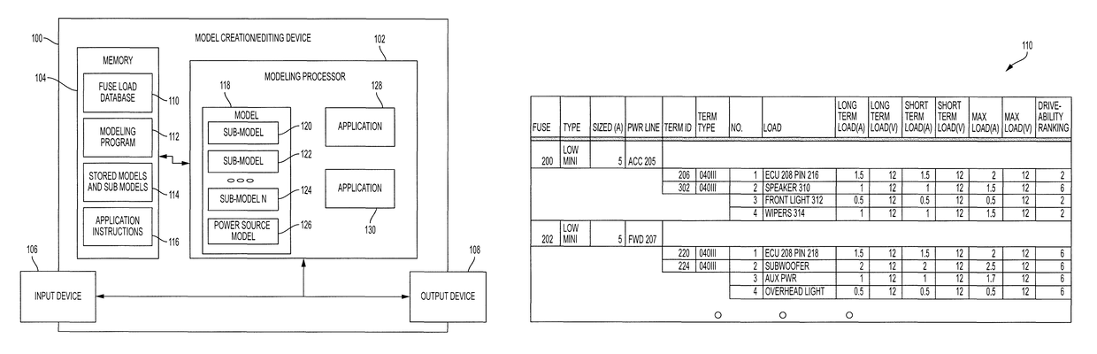
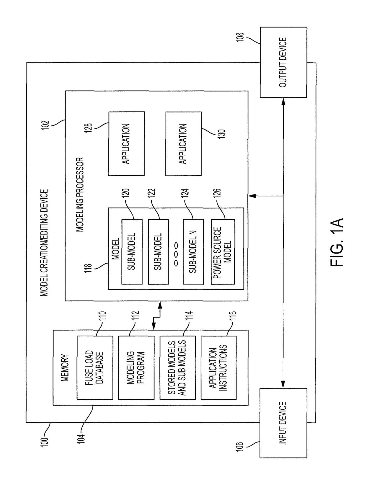
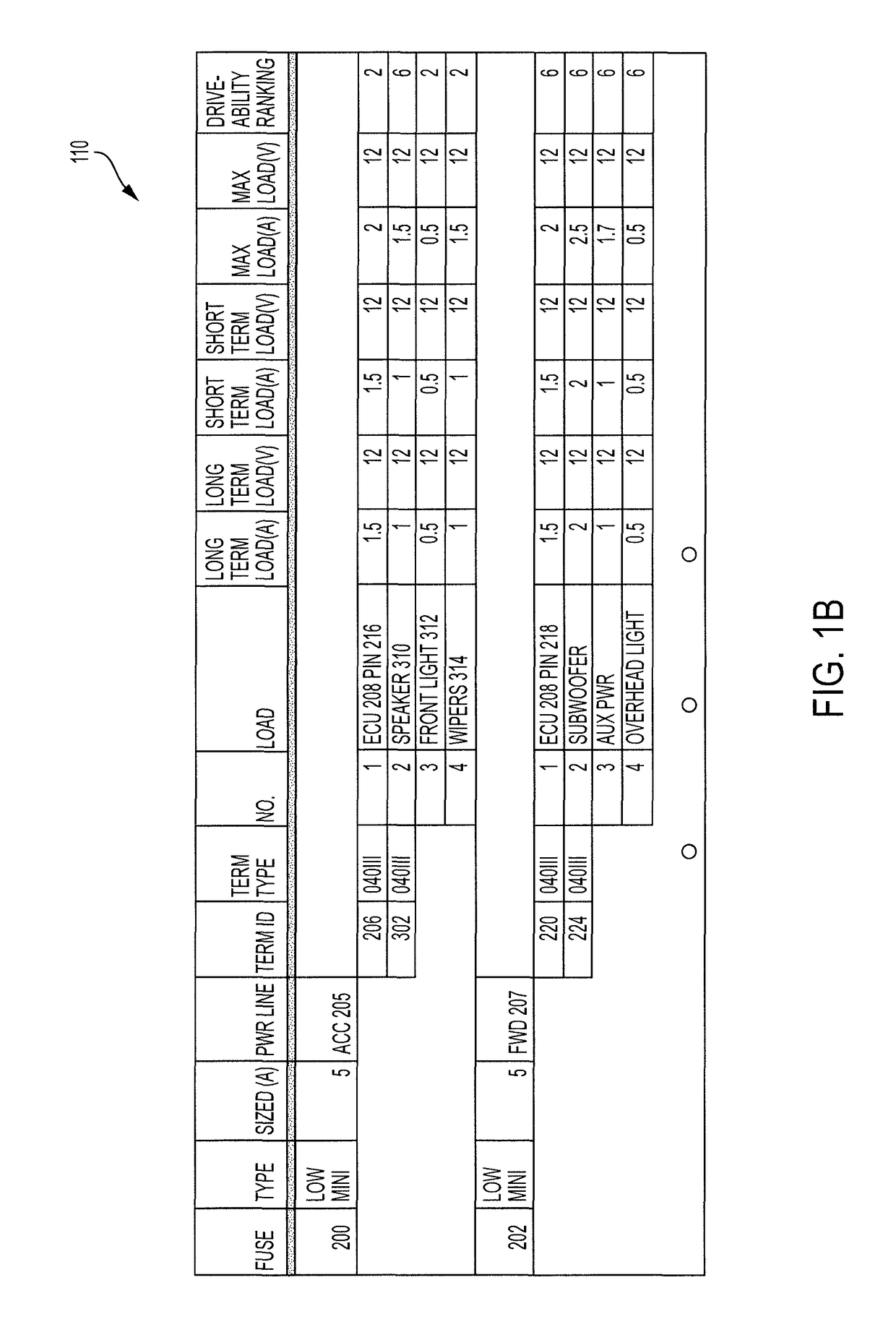
[0024]Disclosed herein are systems and methods for determining whether a total current designed to flow through a fuse of a vehicle is within an acceptable range of current values. This is determined using one or more models of the vehicle. The systems and methods provide several benefits and advantages such as allowing an engineer, designer or other user (“user”) to review summary data associated with the loads of each fuse, such as total current designed to be drawn from any fuse. Allowing a review of this total current provides benefits and advantages such as reducing the likelihood of errors being made during design of vehicle electronic systems and expediting the design process for these electronic systems. The systems and methods provide further benefits and advantages such as allowing the user to review details regarding each load, such as a description of the load, a terminal to which the load is to be connected and various current values associated with the load. The system...


PUM


Abstract

A system can include a memory that can store a fuse load database including a list of fuses, a list of loads each designed to be coupled to at least one fuse from the list of fuses and a list of current values each corresponding to a load from the list of loads. The system can also include an input device configured to receive a selection of a fuse from the list of fuses. The system can also include a modeling processor coupled to the memory and the input device. The modeling processor can determine one or more loads from the list of loads that are designed to be coupled to the selected fuse. The modeling processor can also generate load summary data corresponding to a sum of the current values that correspond to the one or more loads.

Description

BACKGROUND[0001]Field[0002]The present invention relates to systems and methods for identifying loads on fuses of vehicles using a model of the vehicle and, more particularly, for identifying individual and total loads on fuses that are connected to multiple loads from multiple sub-models of the vehicle.[0003]Description of the Related Art[0004]Vehicle engineers and designers (“users”) are increasingly utilizing technological advances to incorporate new capabilities and features into vehicles. For example, electronic control units (ECUs) can control many functions of a vehicle from ignition of engine cylinders and control of transmissions to control of vehicle telematics and infotainment systems. The increase in the use of technology results in more complicated electronic and power systems designs for vehicles. For example, vehicle electronic systems designed 30 years ago may have only included one or two ECUs whereas vehicle electronic systems designed today may include 50 or more ...

Claims


Application Information

Patent Timeline
Patent Type & Authority Patents(United States)
IPC IPC(8): G01R25/00G01R31/07G01R31/74
CPCG01R31/07B60R16/03G01R31/74
Inventor MENG, MING MICHAEL
Owner TOYOTA MOTOR ENG & MFG NORTH AMERICA INC
Features
  • R&D
  • Intellectual Property
  • Life Sciences
  • Materials
  • Tech Scout
  • Unparalleled Data Quality
  • Higher Quality Content
  • 60% Fewer Hallucinations
Learn More