Eyelid shape estimation

a technology of eyelid shape and estimation method, applied in the field of eyelid shape estimation method, can solve the problems of many challenges in the extraction of biometric information, broadly called a biometric template, and achieve the effect of improving the accuracy of eyelid shape estimation

Active Publication Date: 2018-10-02
MAGIC LEAP
View PDF91 Cites 5 Cited by
  • Summary
  • Abstract
  • Description
  • Claims
  • Application Information

AI Technical Summary

Benefits of technology

[0006]In one aspect, a method for eyelid shape estimation is disclosed. The method is performed under control of a hardware computer processor. The method comprises receiving an eye image from an image capture device; generating a shape around the iris of the eye, wherein the shape is tangent to the outermost bounds of the limbic boundary of the eye; generating lines extending from the center of the shape to edges of the shape; applying an edge detection algorithm to the eye image (e.g., the lines extending from the center of the shape) to determine candidate points for a boundary of an eyelid and an iris of the eye; and fitting an eyelid shape curve to at least two candidate points. In another aspect, the method for eyelid shape estimation can be performed by a head mounted display system. In yet another aspect, fitting the eyelid shape curve comprises sampling randomly at lea

Problems solved by technology

The process of extracting biometric information, broadly c

Method used


Image

  • Eyelid shape estimation
  • Eyelid shape estimation
  • Eyelid shape estimation

Examples


example eye -

Example Eye-Box

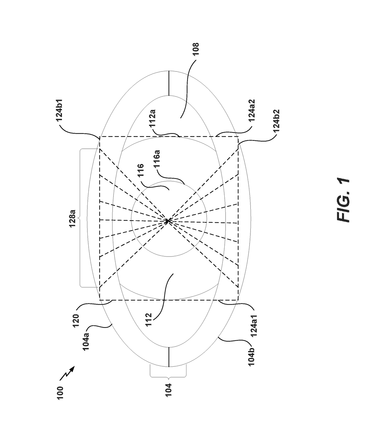
[0021]FIG. 1 illustrates an image of an eye 100 with eyelids 104, sclera 108 (the “white” of the eye), iris 112, and pupil 116. Curve 116a shows the pupillary boundary between the pupil 116 and the iris 112, and curve 112a shows the limbic boundary between the iris 112 and the sclera 108. The eyelids 104 include an upper eyelid 104a and a lower eyelid 104b.

[0022]FIG. 1 also schematically illustrates an example of an eye-box 120 over the eye image of the eye 100 as well as a plurality of radial lines 128a. In various embodiments, the eye-box 120 can be overlaid on the eye 100 in the eye image using processes such as using an image processing algorithm that maps the eye-box 120 to particular portions of the eye image. Overlaying an eye-box 120 on the image of the eye 100 can also be referred to as generating an eye-box 120 or constructing an eye-box 120. As another example, the eye-box 120 can be overlaid on a video using processes such as using a video processing algo...

example wearable

Display System

[0070]In some embodiments, a user device can be wearable, which may advantageously provide a more immersive virtual reality (VR), augmented reality (AR), experience, wherein digitally reproduced images or portions thereof are presented to a wearer in a manner wherein they seem to be, or may be perceived as, real.

[0071]Without being limited by theory, it is believed that the human eye typically can interpret a finite number of depth planes to provide depth perception. Consequently, a highly believable simulation of perceived depth may be achieved by providing, to the eye, different presentations of an image corresponding to each of these limited number of depth planes. For example, displays containing a stack of waveguides may be configured to be worn positioned in front of the eyes of a user, or viewer. The stack of waveguides may be utilized to provide three-dimensional perception to the eye / brain by using a plurality of waveguides to direct light from an image inject...


PUM


Abstract

Systems and methods for eyelid shape estimation are disclosed. In one aspect, after receiving an eye image of an eye (e.g., from an image capture device), an eye-box is generated over an iris of the eye in the eye image. A plurality of radial lines can be generated from approximately the center of the eye-box to an upper edge or a lower edge of the eye box. Candidate points can be determined to have local maximum derivatives along the plurality of radial lines. From the candidate points, an eyelid shape curve (e.g., for an upper eyelid or a lower eyelid) can be determined by fitting a curve (e.g., a parabola or a polynomial) to the candidate points or a subset of the candidate points.

Description

CROSS-REFERENCE TO RELATED APPLICATIONS[0001]This application claims the benefit of priority under 35 U.S.C. § 119(e) to U.S. Provisional Application No. 62 / 208,142, filed on Aug. 21, 2015, entitled “EYELID SHAPE ESTIMATION,” which is hereby incorporated by reference in its entirety.BACKGROUND[0002]Field[0003]The present disclosure relates generally to systems and methods for processing eye imagery.[0004]Description of the Related Art[0005]The human iris can be used as a source of biometric information. Biometric information can provide authentication or identification of an individual. The process of extracting biometric information, broadly called a biometric template, typically has many challenges.SUMMARY[0006]In one aspect, a method for eyelid shape estimation is disclosed. The method is performed under control of a hardware computer processor. The method comprises receiving an eye image from an image capture device; generating a shape around the iris of the eye, wherein the sha...

Claims


Application Information

Patent Timeline
IPC IPC(8): G06K9/00G06V30/144
CPCG06K9/00597G06K9/0061G06V40/171G06V40/193G06V40/18
Inventor AMAYEH, GHOLAMREZAKAEHLER, ADRIAN
Owner MAGIC LEAP
Why Eureka
Try Eureka