Check patentability & draft patents in minutes with Patsnap Eureka AI!

Drive unit for marine vessels comprised of drive shaft braking and locking system

a technology of marine vessels and drive shafts, applied in marine propulsion, vessel construction, transportation and packaging, etc., can solve the problems of inability to rotate the drive shaft of the failed drive unit, damage to the drive shaft's roller bearing of the drive unit, etc., to avoid the risk of dust or unit heating up

Active Publication Date: 2020-07-14
AETC SAPPHIRE
View PDF8 Cites 0 Cited by
  • Summary
  • Abstract
  • Description
  • Claims
  • Application Information

AI Technical Summary

Benefits of technology

[0008]At the front of the drive unit there are at least two braking and locking systems located between the upstream roller bearing and propulsion element. When the drive unit is immersed, the area between the upstream rolling bearing and propulsion element is filled with sea water. Braking and locking systems are placed within the drive unit and are immersed in this area. This helps avoid any risk of dust or the unit heating up when braking and / or locking the drive shaft.

Problems solved by technology

Due to strong currents, the propeller of the ship's drive unit can inadvertently damage the drive shaft's roller bearing of the drive unit.
Furthermore, in strong currents, it may be necessary to brake, or block, the drive shaft of the drive unit propeller.
Additionally, if one of the propulsion units fails, the drive shaft rotation of the failed drive unit must be blocked.

Method used


Image

  • Drive unit for marine vessels comprised of drive shaft braking and locking system
  • Drive unit for marine vessels comprised of drive shaft braking and locking system

Examples


Embodiment Construction

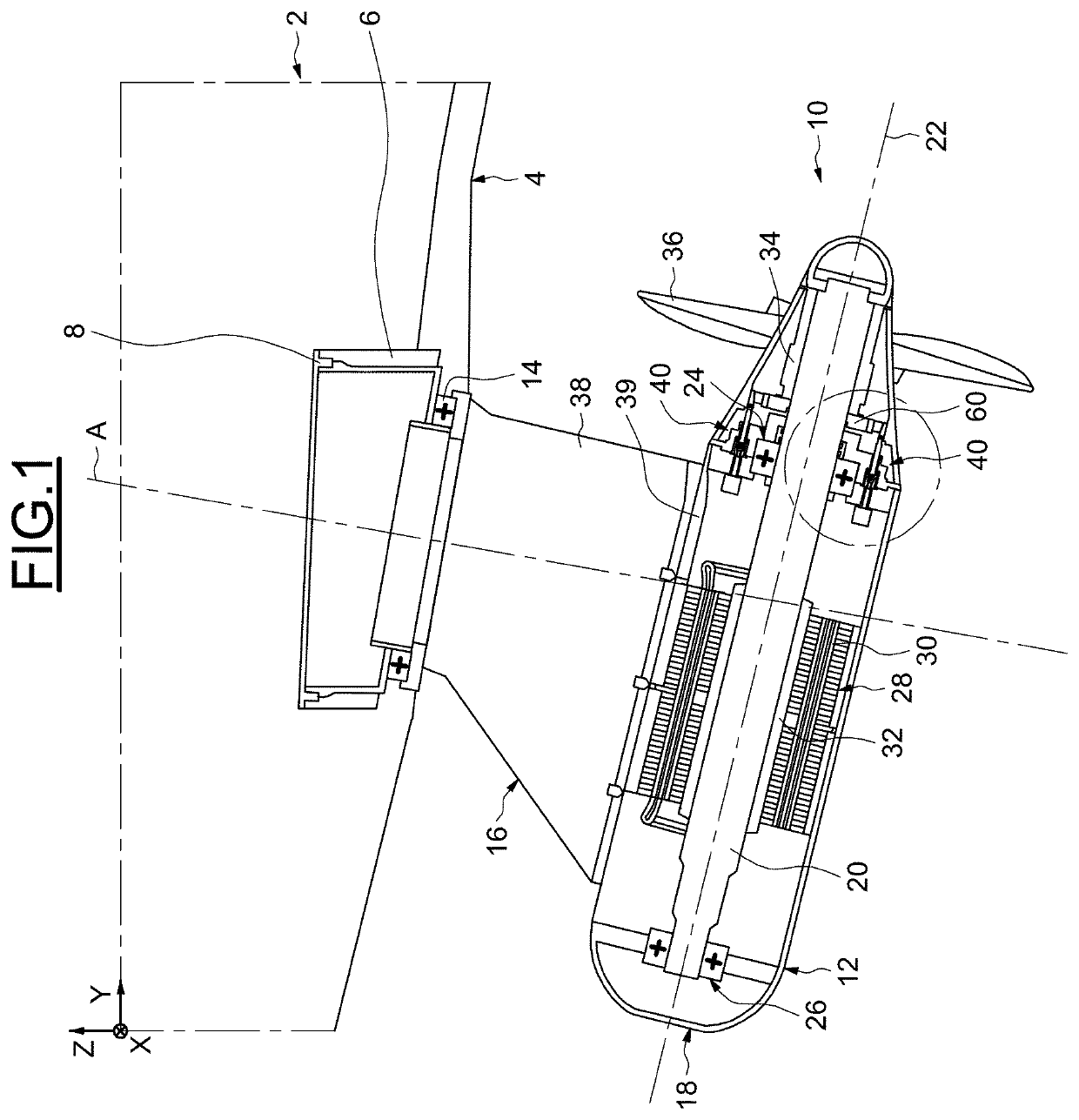
[0021]In the following description, the terms “longitudinal”, “transverse”, “vertical”, “front”, “back”, “left”, and “right” are designated in relation to the common orthogonal benchmark of marine vessels represented in figures, including:

[0022]a. An X axis, perpendicular to the plane of FIG. 1 and oriented by the marine vessel pitch axis 2, while the marine vessel is disposed according to a normal operating plan. A “normal operating plane” contains longitudinal and transversal marine vessel directions while the latter evolves on a calm sea, under normal loading conditions.

[0023]b. A Y axis, horizontal relative to FIG. 1 and oriented by the marine vessel pitch axis, while the marine vessel is disposed according to a normal operating plan.

[0024]c. A Z axis, vertical relative to FIG. 1 and oriented by the marine vessel yaw axis, while the marine vessel is disposed according to a normal operating plan.

[0025]“Marine vessels” refers to ships, submarines, or oil platforms.
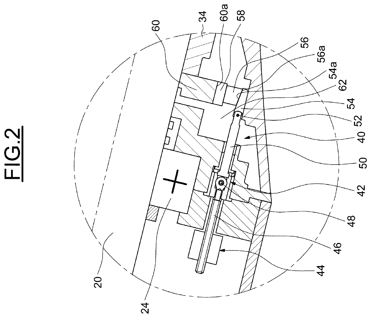
[0026]As illustr...


PUM


Abstract

The drive unit is designed to be mounted on a marine vessel, including a mobile housing, and is able to pivot around an axis against the hull of the marine vessel. A drive shaft mounted rotary is against the mobile housing and is supported by two roller bearings. A propulsion element rotates in solidarity with the drive shaft. The propulsion unit has, at the front, at least two braking and locking systems of the drive shaft located in an area between the upstream rolling bearing and propulsion element.

Description

BACKGROUND OF THE DISCLOSURE[0001]The proposed invention concerns the drive units of marine vessels such as ships or submarines, as well as oil platforms.[0002]These drive units, also known as “propulsion oriented drive” or “POD”, typically include a mobile housing mounted with a pivot link to a hull of a marine vessel. The hull element may be placed at the stern or prow of a ship.[0003]Due to strong currents, the propeller of the ship's drive unit can inadvertently damage the drive shaft's roller bearing of the drive unit. Furthermore, in strong currents, it may be necessary to brake, or block, the drive shaft of the drive unit propeller.[0004]Additionally, if one of the propulsion units fails, the drive shaft rotation of the failed drive unit must be blocked. This allows the ship to return to port using the working drive unit, preventing further damage to the defective drive unit.[0005]Drive units used for ice-breaking have an additional axial dimension constraint, which means it ...

Claims


Application Information

Patent Timeline
Patent Type & Authority Patents(United States)
IPC IPC(8): B63H23/35F16C41/00F16D49/18B63H21/17B63H25/42F16D49/00B63H5/125F16D125/40F16D125/66
CPCB63H25/42F16C41/001B63H23/35F16D49/00B63H5/125B63H21/17F16D49/18B63H2005/1256F16D2125/40F16C2326/30F16D2125/66
Inventor VINCENT, LOICDESCHAMPS, THIERRYBARTH, LAURENTJULLIAND, LIONEL
Owner AETC SAPPHIRE
Features
  • R&D
  • Intellectual Property
  • Life Sciences
  • Materials
  • Tech Scout
  • Unparalleled Data Quality
  • Higher Quality Content
  • 60% Fewer Hallucinations
Learn More