Channels and lenses for linear lighting

a linear luminaire and lens technology, applied in the field of lighting, can solve problems such as the convergence of emission light rays

Active Publication Date: 2021-11-09
ELEMENTAL LED
View PDF12 Cites 4 Cited by
  • Summary
  • Abstract
  • Description
  • Claims
  • Application Information

AI Technical Summary

Benefits of technology

[0007]Another aspect of the invention relates to a cover for diffusing light emitted by linear lighting. The cover comprises an optically-transmissive material with a diffusing additive. In one embodiment, the diffusing additive is distributed uniformly within the optically-transmissive material. In order to provide more diffusion where emitted light intensity is greatest, the cover is thickest where the light intensity is expected to be greatest, and implements a gradient such that it is thinnest where the emitted light intensity is expected to be weakest. In an embodiment where the linear lighting is expected to be centered in the channel, this results in a cover-lens with a plano-convex shape. However, in at least some embodiments, the plano-convex shape of the cover-lens would undesirably cause the emitted light rays to converge. Therefore, the cover-lens may also implement Fresnel-style grooves arranged to cause the emitted light to diverge and spread, counteracting at least some of the effect of the underlying plano-convex shape.

Problems solved by technology

However, in at least some embodiments, the plano-convex shape of the cover-lens would undesirably cause the emitted light rays to converge.

Method used


Image

  • Channels and lenses for linear lighting
  • Channels and lenses for linear lighting
  • Channels and lenses for linear lighting

Examples


Embodiment Construction

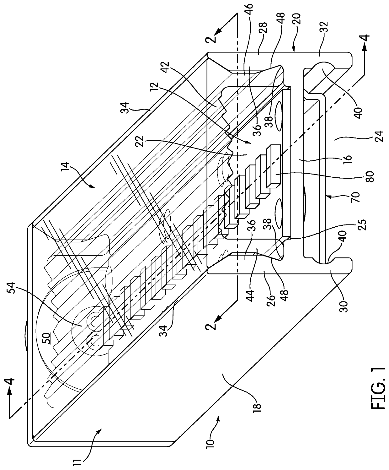
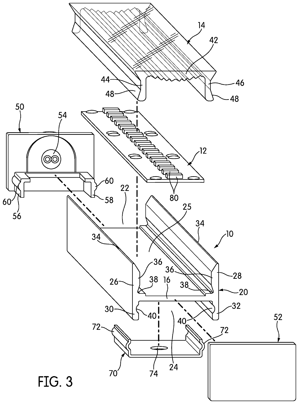
[0021]FIG. 1 is a perspective view of a luminaire, generally indicated at 10, shown with one end open for purposes of illustration. The luminaire 10 includes a channel 11, which is shown with a strip of linear lighting 12 installed, and is covered with a cover-lens 14, as will be described below in more detail.

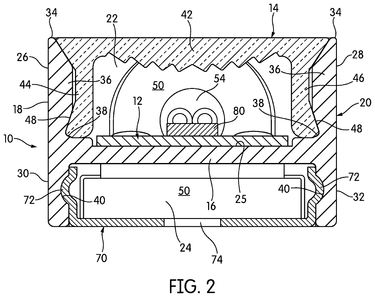
[0022]The channel 11 has a generally H-shaped cross-section, with a cross-member 16 extending generally horizontally between two sidewalls 18, 20. The cross-member 16 and sidewalls 18, 20 define two compartments in the channel 11: an upper compartment 22, in which the linear lighting 12 is installed, and a lower compartment 24. With respect to the coordinate system of FIG. 1, the upper compartment 22 opens up, and the lower compartment opens down. As can be seen in FIG. 1, the cross-member 16 is not vertically centered along the sidewalls 18, 20; its position below the horizontal centerline of the channel 11 makes the upper compartment 22 deeper than the lower compartment 24. ...


PUM

PropertyMeasurementUnit
lengthaaaaaaaaaa
lengthaaaaaaaaaa
voltagesaaaaaaaaaa

Abstract

Channels and channel covers for linear lighting are disclosed. The channels have an upper compartment for linear lighting and a lower compartment that may be used as a raceway, to engage parts, and for rear entry of wires. Endcaps for the channels may engage the lower compartment. Cover-lenses for linear lighting channels are also disclosed. The cover-lenses may include diffusing material and implement a thickness gradient in order to maximize the amount of diffusing material where the emitted light intensity is expected to be greatest. Diverging Fresnel features may be superimposed on the thickness gradient in order to counteract any converging effect of the thickness gradient and cause emitted light to spread more evenly.

Description

CROSS-REFERENCE TO RELATED APPLICATIONS[0001]This application is a continuation of U.S. application Ser. No. 17 / 130,935, filed Dec. 22, 2020, which claims priority to, and the benefit of, U.S. Provisional Patent Application No. 63 / 037,885, filed Jun. 11, 2020. The contents of those applications are incorporated by reference herein in their entirety.TECHNICAL FIELD[0002]The invention relates to lighting in general, and in particular, to linear luminaires.BACKGROUND[0003]Linear lighting is a particular type of solid-state lighting that uses light-emitting diodes (LED). In this type of lighting, a long, narrow printed circuit board (PCB) is populated with LED light engines, usually spaced at a regular pitch or spacing. The PCB may be either rigid or flexible, and other circuit components may be included on the PCB, if necessary. Depending on the type of LED light engine or engines that are used, the linear lighting may emit a single color, or may be capable of emitting multiple colors....

Claims


Application Information

Patent Timeline
Patent Type & Authority Patents(United States)
IPC IPC(8): F21S4/00F21S4/28F21V5/04F21V3/10F21V23/00F21Y103/10
CPCF21S4/28F21V3/10F21V5/045F21V23/002F21Y2103/10F21Y2115/10
Inventor IRONS, TRAVISGREEN, ROBERTGREENSPAN, DAVID
Owner ELEMENTAL LED
Why Eureka
Try Eureka