Pneumatic tire

a technology of pneumatic tires and tires, applied in the field of pneumatic tires, can solve the problems of deteriorating rolling resistance and increasing weight, and achieve the effect of suppressing weight and rolling resistan

Active Publication Date: 2021-12-14
TOYO TIRE & RUBBER CO LTD
View PDF11 Cites 0 Cited by
  • Summary
  • Abstract
  • Description
  • Claims
  • Application Information

AI Technical Summary

Benefits of technology

[0005]The present invention has been made with the above-described circumstances in view and its object is to provide a pneumatic tire with which cutting resistance and puncture resistance of the tire can be secured while increase in weight and rolling resistance of the tire is suppressed.
[0015]With this structure, it is possible to obtain cutting resistance and puncture resistance, because the first ply and the second ply are disposed at a shoulder portion positioned on the outside in the mounting to the vehicle, the shoulder portion liable to receive side cuts as a result of contact with edge stones and the like. Because the second ply is not disposed at a portion to which tension is not applied, and specifically, on an inner peripheral side of the belt layer, it is possible to suppress increase in weight and rolling resistance. Furthermore, by relatively increasing the tensile strength of the second ply close to a tire outer surface and relatively decreasing the tensile strength of the first ply far from the tire outer surface in the shoulder portion positioned on the outside in the mounting to the vehicle, it is possible to effectively suppress increase in weight and rolling resistance due to the first ply while securing sufficient cutting resistance and puncture resistance with the second ply.
[0017]By providing the third ply, a rigidity difference between left and right sides of the pneumatic tire decreases, which improves steering stability.
[0019]With this structure, the rigidity difference between the left and right sides of the pneumatic tire further decreases, which further improves the steering stability.
[0021]By relatively decreasing the tensile strength of the third ply disposed in the sidewall portion positioned on the inside in the mounting to the vehicle, it is possible to suppress increase in weight and rolling resistance due to the third ply.

Problems solved by technology

However, the carcass layer formed by the two carcass plies increases a weight and deteriorates a rolling resistance.

Method used


Image

  • Pneumatic tire
  • Pneumatic tire

Examples


examples

[0046]Examples specifically showing the structures and the effects of the present invention will be described below. Properties to be evaluated of the examples and the like were measured as follows.

[0047](1) External Damage Resistance

[0048]To evaluate resistance against a side burst that occurs when a tire runs over a protrusion such as an edge stone, each test tire was mounted to a real car, the real car drove into a road with the side stones and ran over the protrusion, and presence or absence of a failure of a tire side portion was checked. The vehicle speed was increased from 10 Km / h and an evaluation was made by a speed at which the failure occurred. The index evaluation was made with respect to an index 100 indicating a result of Comparative Example 1. The higher the value, the higher the speed at which the failure was found, i.e., the more excellent in external damage resistance.

[0049](2) Rolling Resistance

[0050]Each tire of a size of 225 / 65R17 102H was mounted to a rim and t...

examples 1 to 3

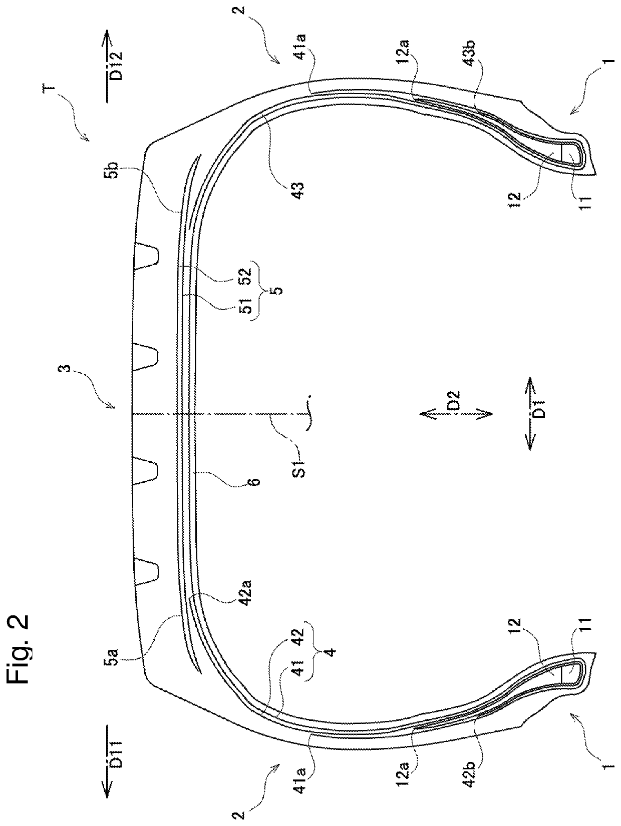
[0053]Examples 1 to 3 were tires according to the embodiment shown in FIG. 2. When tensile strength of a second carcass ply 42 was defined as A, tensile strength of a first carcass ply 41 was defined as B, and tensile strength of a third carcass ply 43 was defined as C, Example 1 satisfied A=C>B, Example 2 satisfied A>B=C, and Example 3 satisfied A>B>C. A value of B in each of Examples 1 to 3 was equal to that in Comparative Example 1 (described later). The evaluations were made by using the tires and results of the evaluations are shown in Table 1.

example 4

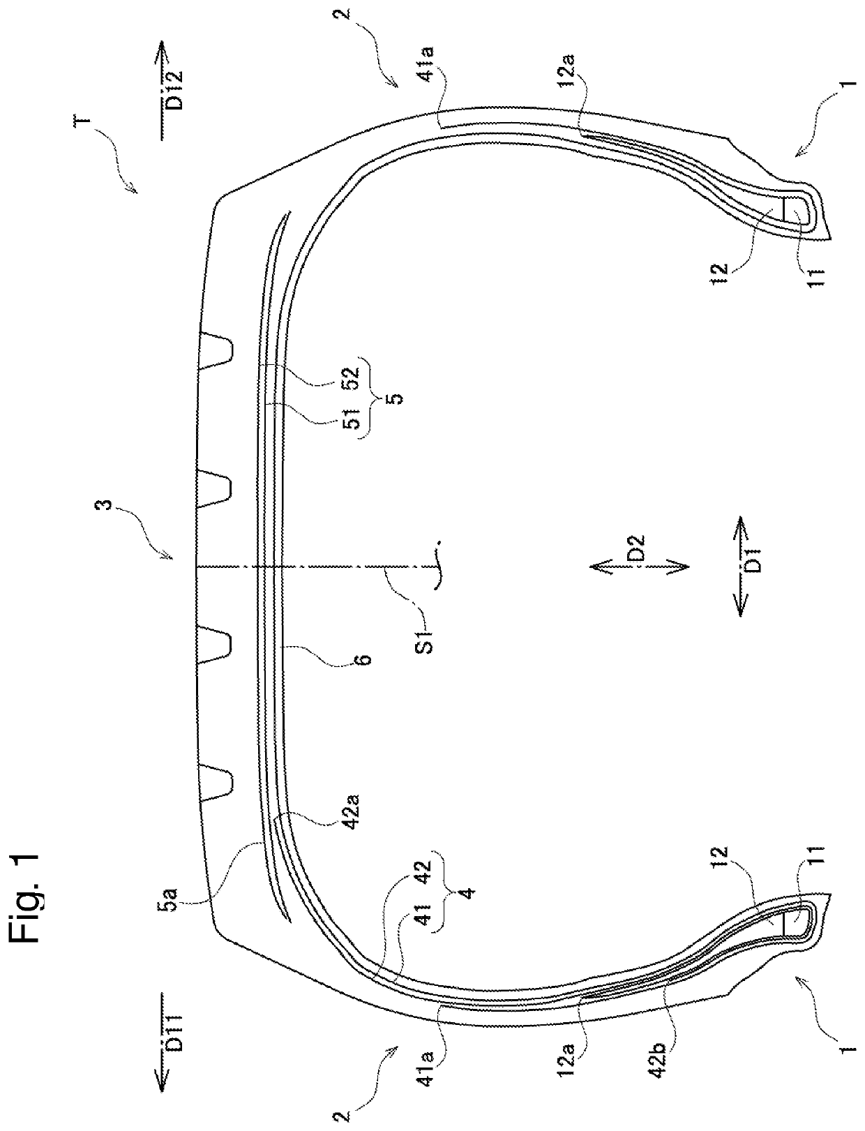
[0054]Example 4 was a tire according to the embodiment shown in FIG. 1. Example 4 satisfied A>B. A value of B in Example 4 was equal to that in Comparative Example 1 (described later). The evaluations were made by using the tires and results of the evaluations are shown in Table 1.


PUM

PropertyMeasurementUnit
pressureaaaaaaaaaa
air pressureaaaaaaaaaa
widthaaaaaaaaaa

Abstract

A pneumatic tire includes: paired bead portions respectively including annular bead cores and bead fillers disposed on an outer side in a tire radial direction of the bead cores; sidewall portions respectively extending outward in the tire radial direction from the bead portions; a tread portion connected to outer ends in the tire radial direction of the sidewall portions to form a tread; a carcass layer suspended between the bead portions; and a belt layer provided on an outer side in the tire radial direction of the carcass layer in the tread portion. The carcass layer has a first ply that continuously extends between the bead portions and that has opposite end portions and a second ply that extends from a position in contact with an inner peripheral face of an end portion, wherein the second ply has higher tensile strength than the tensile strength of the first ply.

Description

BACKGROUND OF THE INVENTIONField of the Invention[0001]The present invention relates to a pneumatic tire and particularly to a pneumatic tire including a carcass layer formed by two or more carcass plies.Description of the Related Art[0002]A general pneumatic tire includes paired bead portions, sidewall portions respectively extending outward in a tire radial direction from the bead portions, a tread portion connected to outer ends in the tire radial direction of the sidewall portions to form a tread, and a carcass layer suspended between the paired bead portions.[0003]In a case of a pneumatic tire used under severe conditions such as traveling on a rough road, a carcass layer may be formed by two carcass plies in some cases in order to secure cutting resistance and puncture resistance (see Patent Document 1 below, for example). However, the carcass layer formed by the two carcass plies increases a weight and deteriorates a rolling resistance.PRIOR ART DOCUMENTPatent Document[0004]P...

Claims


Application Information

Patent Timeline
Patent Type & Authority Patents(United States)
IPC IPC(8): B60C15/00B60C15/06B60C9/08B60C9/02B60C19/00B60C9/04
CPCB60C15/0036B60C9/023B60C9/08B60C15/0009B60C15/0054B60C15/06B60C19/001B60C2009/045B60C2015/009B60C2015/061B60C2015/0614
Inventor SAKATA, HIROKAZU
Owner TOYO TIRE & RUBBER CO LTD
Why Eureka
Try Eureka