
Play yard
a play yard and play technology, applied in the field of play yards, can solve the problems of inconvenience for parents or care givers, and achieve the effect of convenient operation for users
- Summary
- Abstract
- Description
- Claims
- Application Information
AI Technical Summary
Benefits of technology
Problems solved by technology
Method used
Image

Examples
Embodiment Construction
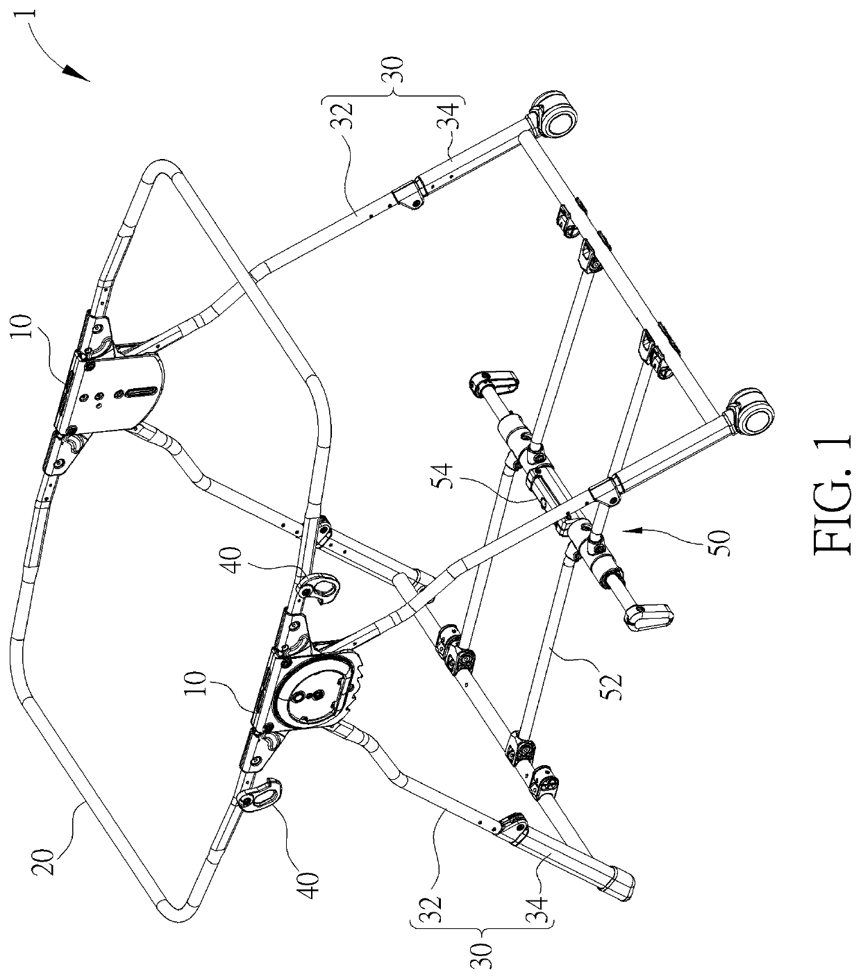
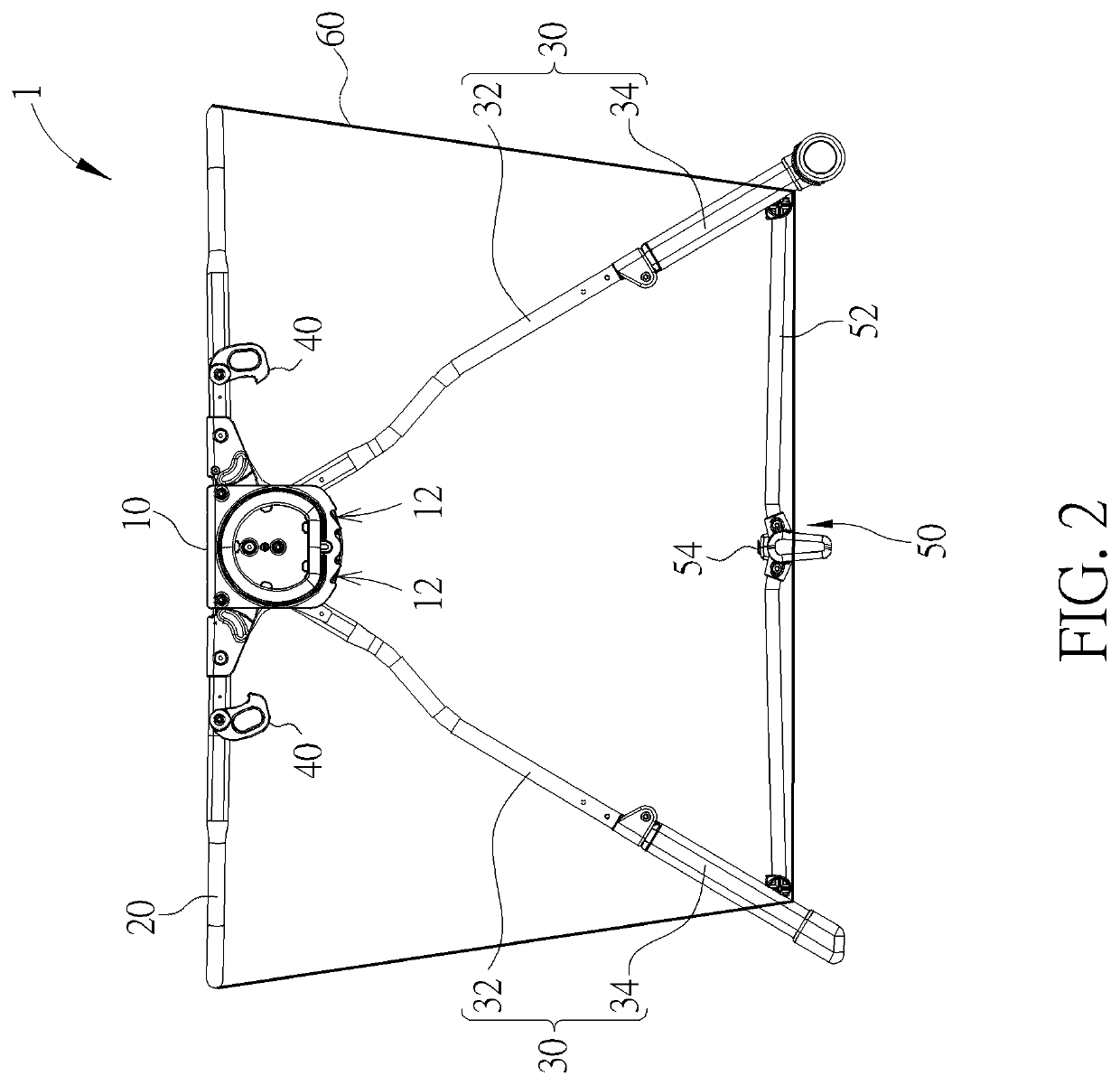
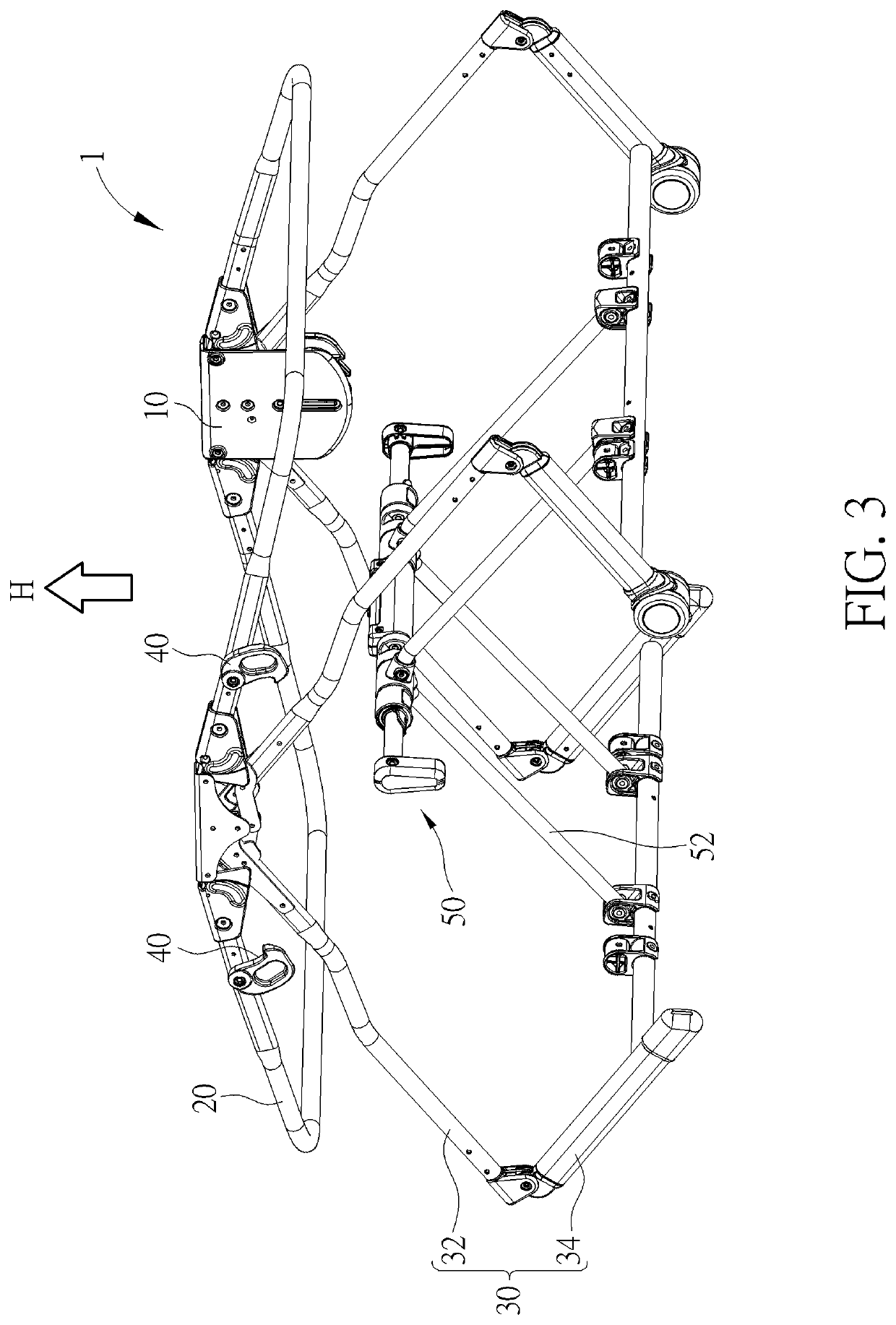
[0016]Please refer to FIG. 1 to FIG. 3, FIG. 1 is a perspective view of a play yard 1 according to an embodiment of the invention, FIG. 2 is a side view illustrating the play yard 1 shown in FIG. 1 with a softgoods clothing, and FIG. 3 is a perspective view illustrating the central member 50 shown in FIG. 1 being lifted.
[0017]The play yard 1 can be configured to an unfolded position (as shown in FIG. 1) or a folded position (the fully folded position of the play yard 1 in part is shown in FIG. 10). As shown in FIG. 1, the play yard 1 includes two brackets 10, two rail members 20, two support frames 30, two engaging members 40, a central member 50, a plurality of connecting members 52, and a latch mechanism 54. The rail members 20 are pivotally connected to the brackets 10. Each of the support frames 30 includes two upper support members 32 and a lower support member 34. The upper support members 32 are pivotally connected to the brackets 10 and the lower support member 34 is pivotal...
PUM
 Abstract
Description
Claims
Application Information