Tool box

a tool box and tool technology, applied in the field of tool boxes, can solve problems such as inconvenience for users, and achieve the effect of convenient user removal of hand tools, easy and rapid removal of hand tools

Inactive Publication Date: 2006-04-04
CHEN CHANG YING
View PDF6 Cites 23 Cited by
  • Summary
  • Abstract
  • Description
  • Claims
  • Application Information

AI Technical Summary

Benefits of technology

[0005]The primary objective of the present invention is to provide a tool box that facilitates the user removing the hand tool, so that the user can take the hand tool from the tool box easily and rapidly.
[0006]Another objective of the present invention is to provide a tool box, wherein when the top cover is entirely removed from the base, the receiving rack is lifted to the optimum inclined position, so that the user can take the screwdriver tips from the receiving rack easily and conveniently.
[0007]A further objective of the present invention is to provide a tool box, wherein the pivotal block and the movable block of the receiving rack are separated from each other by the restoring force of the two elastic plates so as to form a larger space, thereby facilitating the user removing the screwdriver tips from the pivotal block and the movable block of the receiving rack.
[0008]A further objective of the present invention is to provide a tool box, wherein the secondary receiving rack is moved in concert with the receiving rack by connection of the link, thereby facilitating the user removing the screwdriver tips from the secondary receiving rack.

Problems solved by technology

However, the receiving portions are fixed in the main body without movement, thereby causing inconvenience to the user when removing the hand tools from the receiving portions of the main body.

Method used


Image

  • Tool box
  • Tool box
  • Tool box

Examples


Embodiment Construction

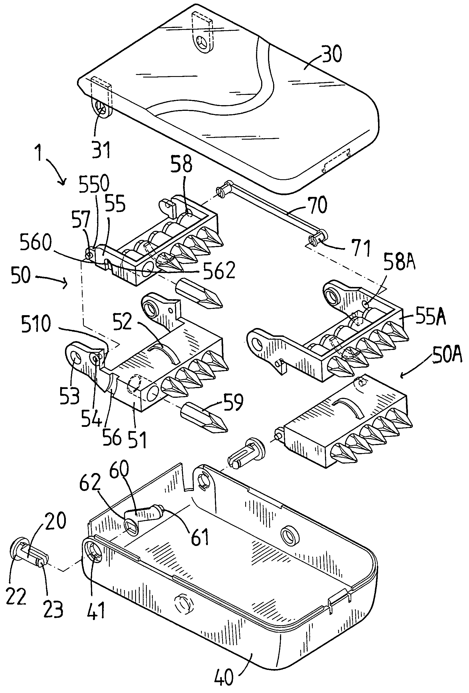
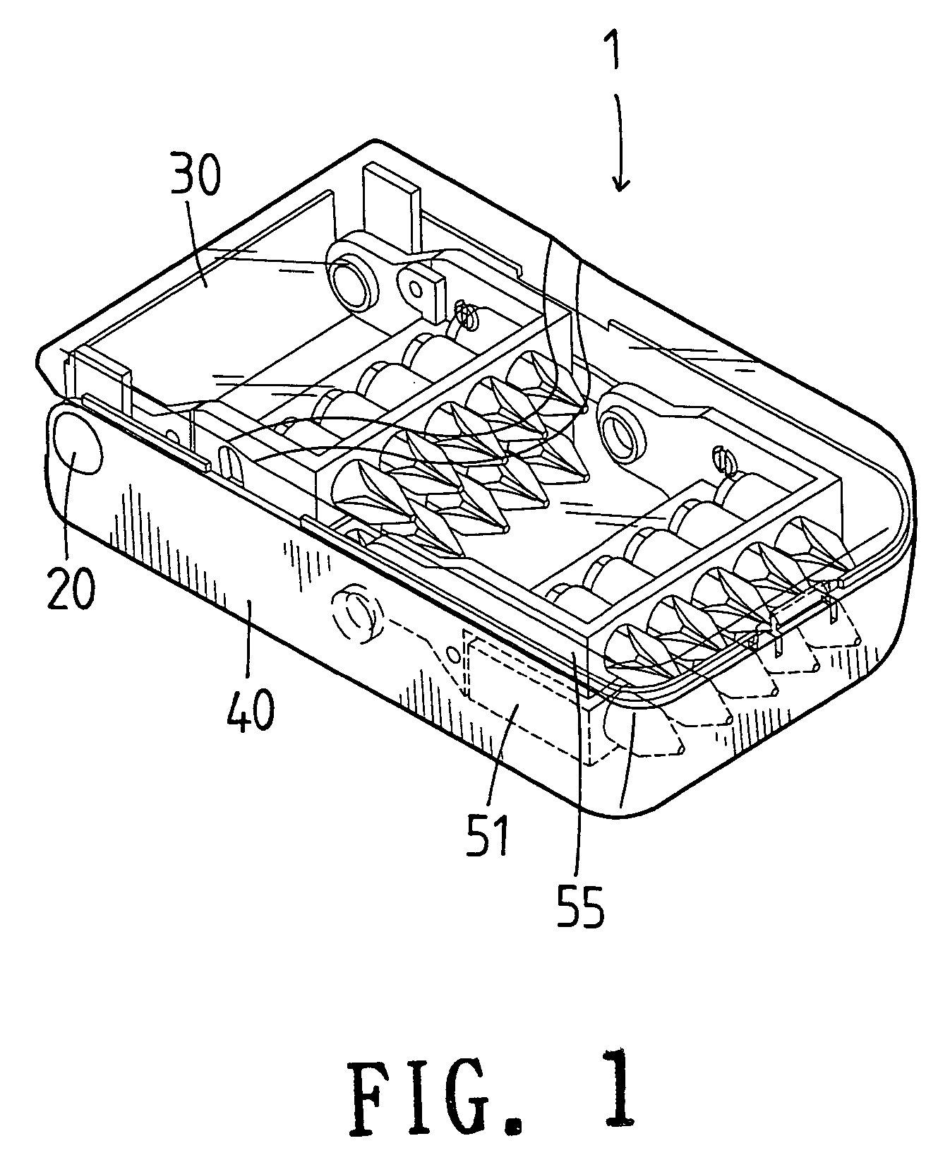
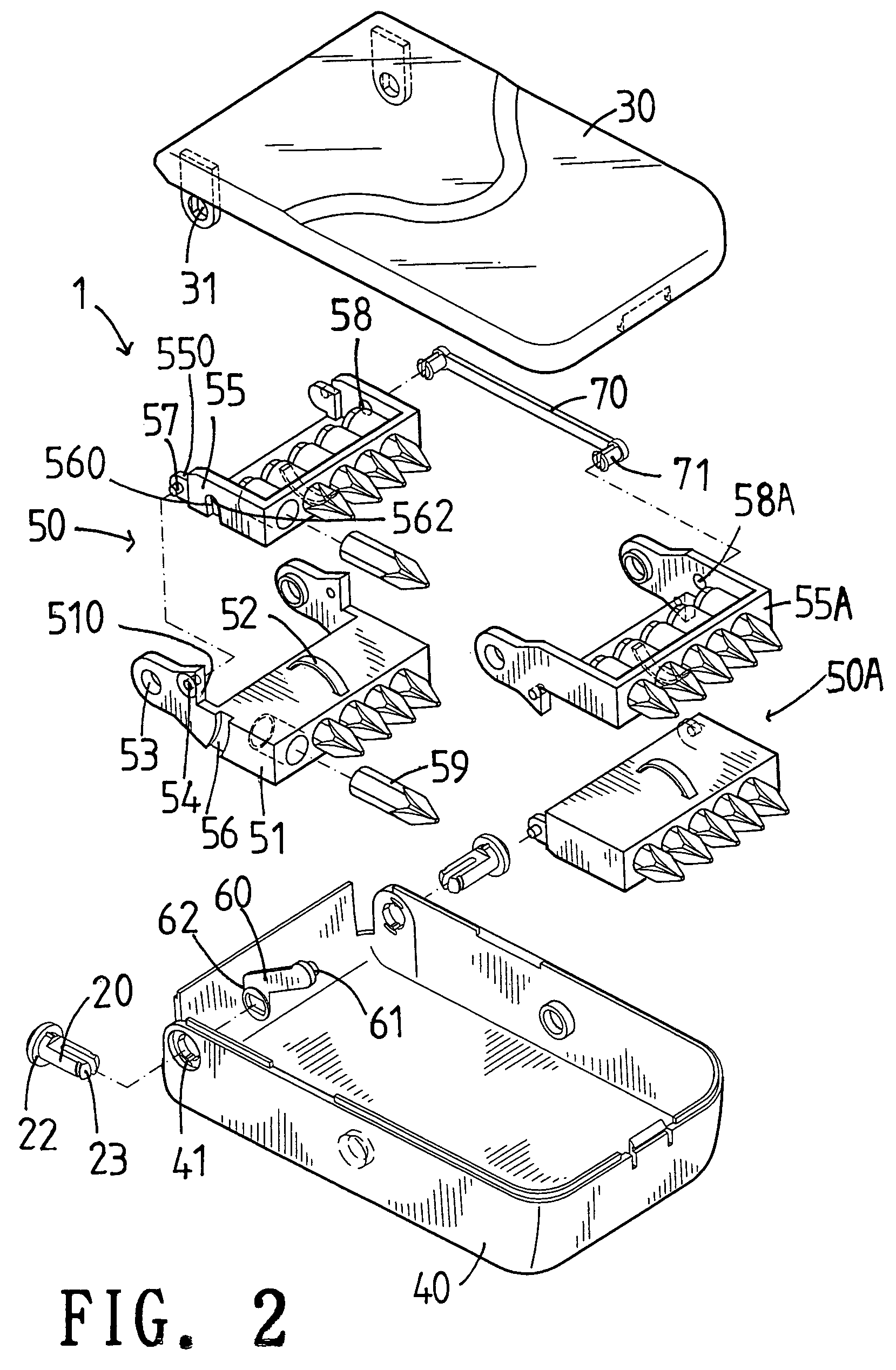
[0025]Referring to the drawings and initially to FIGS. 1–3, a tool box in accordance with the preferred embodiment of the present invention comprises a base 40, a top cover 30 pivotally mounted on the base 40, a receiving rack 50 pivotally mounted in the base 40 for receiving a plurality of hand tools, such as the screwdriver tips 59, and a driving lever 60 pivotally mounted in the base 40 and having a first end connected to and driven by the top cover 30 and a second end connected to the receiving rack 50 for moving the receiving rack 50.

[0026]The receiving rack 50 includes a pivotal block 51 pivotally mounted in the base 40, and a movable block 55 pivotally mounted on the pivotal block 51.

[0027]The base 40 has two sides each formed with a through hole 41, the top cover 30 has two sides each formed with a driving hole 31, the first end of the driving lever 60 is formed with a driven hole 62, the pivotal block 51 of the receiving rack 50 has two sides each formed with a through hole...


PUM


Abstract

A tool box includes a base, a top cover pivotally mounted on the base, a receiving rack pivotally mounted in the base for receiving a plurality of hand tools, and a driving lever pivotally mounted in the base and having a first end connected to and driven by the top cover and a second end connected to the receiving rack for moving the receiving rack. Thus, when the top cover is removed from the base, the receiving rack is lifted to the optimum inclined position, so that the user can take the screwdriver tips from the receiving rack easily and conveniently.

Description

BACKGROUND OF THE INVENTION[0001]1. Field of the Invention[0002]The present invention relates to a tool box, and more particularly to a removable tool box that facilitates the user removing the hand tool, so that the user can take the hand tool from the tool box easily and rapidly.[0003]2. Description of the Related Art[0004]A conventional tool box comprises a main body having a plurality of receiving portions for receiving and clamping the hand tools, such as the screwdriver tips or the like, and a cover pivotally mounted on the main body. Thus, the user can remove the hand tools from the receiving portions of the main body by pivoting the cover outward relative to the main body. However, the receiving portions are fixed in the main body without movement, thereby causing inconvenience to the user when removing the hand tools from the receiving portions of the main body.SUMMARY OF THE INVENTION[0005]The primary objective of the present invention is to provide a tool box that facilit...

Claims


Application Information

Patent Timeline
Patent Type & Authority Patents(United States)
IPC IPC(8): B65D85/20B25H3/00B65D85/28
CPCB25H3/003
Inventor CHEN, CHANG-YING
Owner CHEN CHANG YING
Why Eureka
Try Eureka