

Method for the production of functionalised short carbon nanotubes and functionalised short carbon nanotubes obtainable by said method
- Summary
- Abstract
- Description
- Claims
- Application Information
AI Technical Summary
Benefits of technology
Problems solved by technology
Method used
Image

Examples
case 1
[0114] 2. MWNTs
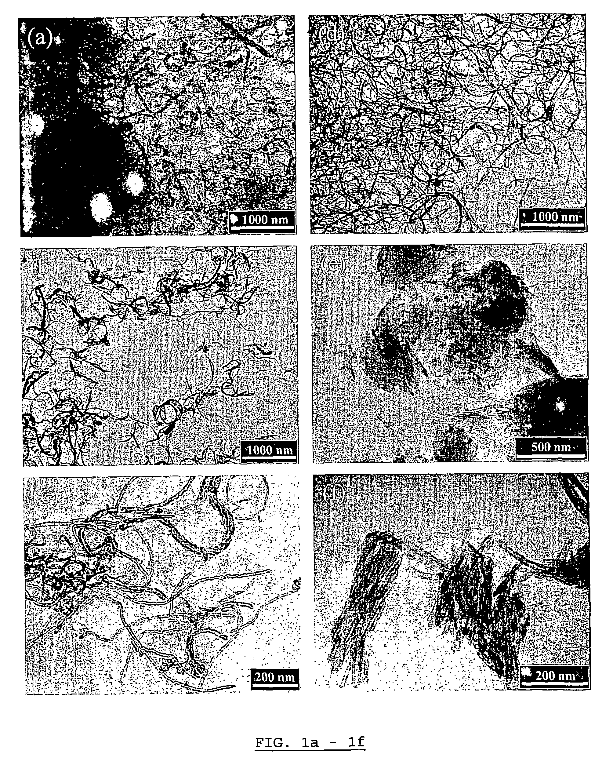
[0115] Long very thin MWNTs were firstly synthesised according to the method described in the part entitled "Production of long carbon nanotubes", by catalytic decomposition of acetylene at 700.degree. C. using a mixture of Fe / Co 1.6% / 1.6% supported on Al.sub.2O.sub.3 as catalyst. The acetylene flow was 30 ml / min and N.sub.2 was used as carrier gas at a flow of 300 ml / min. The crude very thin MWNTs thus obtained were containing 80.2 wt % of carbon. They had closed tips, were approximately 10 .mu.m in length, had an average inner / outer diameter of 5 / 10 nm and had an average number of layers of 8.
[0116] Three samples were tested from these crude long MWNTs:
[0117] sample 1 containing long MWNTs as such;
[0118] sample 2 and sample 3 wherein 4 g fractions of long MWNTs were submitted to ball milling according to the method of the invention during 24 hours.
[0119] The three samples, sample 1, sample 2 and sample 3, were studied for their He and H.sub.2 adsorption abilities a...
PUM
 Abstract
Description
Claims
Application Information