

Plasma CVD device
a plasma cvd and flat-type technology, applied in the field of parallel-flat-type plasma cvd (), can solve the problems of particle formation and failure of reaction by-products of poor adhesive strength
- Summary
- Abstract
- Description
- Claims
- Application Information
AI Technical Summary
Benefits of technology
Problems solved by technology
Method used
Image

Examples
first embodiment
[0099] FIG. 3 is a lateral cross-sectional diagram illustrating an example of the detailed structure of the It should be pointed out that the drawing shows the present embodiment adapted to a plasma CVD device having a vacuum container with a twin-tank structure.
[0100] The plasma CVD device illustrated in the drawing has a vacuum container 400 with a twin-tank structure. This vacuum container 400 has an outer tank body 401 which forms the side walls and bottom plate of the outer tank, an inner tank body 402 which forms the side walls and bottom plate of the inner tank, and a top plate 403 which is shared by both the outer and inner tanks.
[0101] In the side walls of the outer tank are a conveyance inlet 11a and a conveyance outlet 12a for the treatment substrate W. These are closed by gate valves 410, 420 respectively.
[0102] In the interior of the inner tank are located an upper electrode 430 and a lower electrode 440. These are arranged horizontally and in such a manner as to face ...
second embodiment
[0147] 2. Second Embodiment
[0148] 2.1 Structure
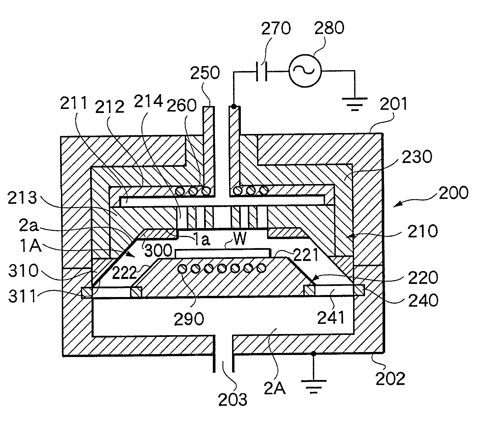
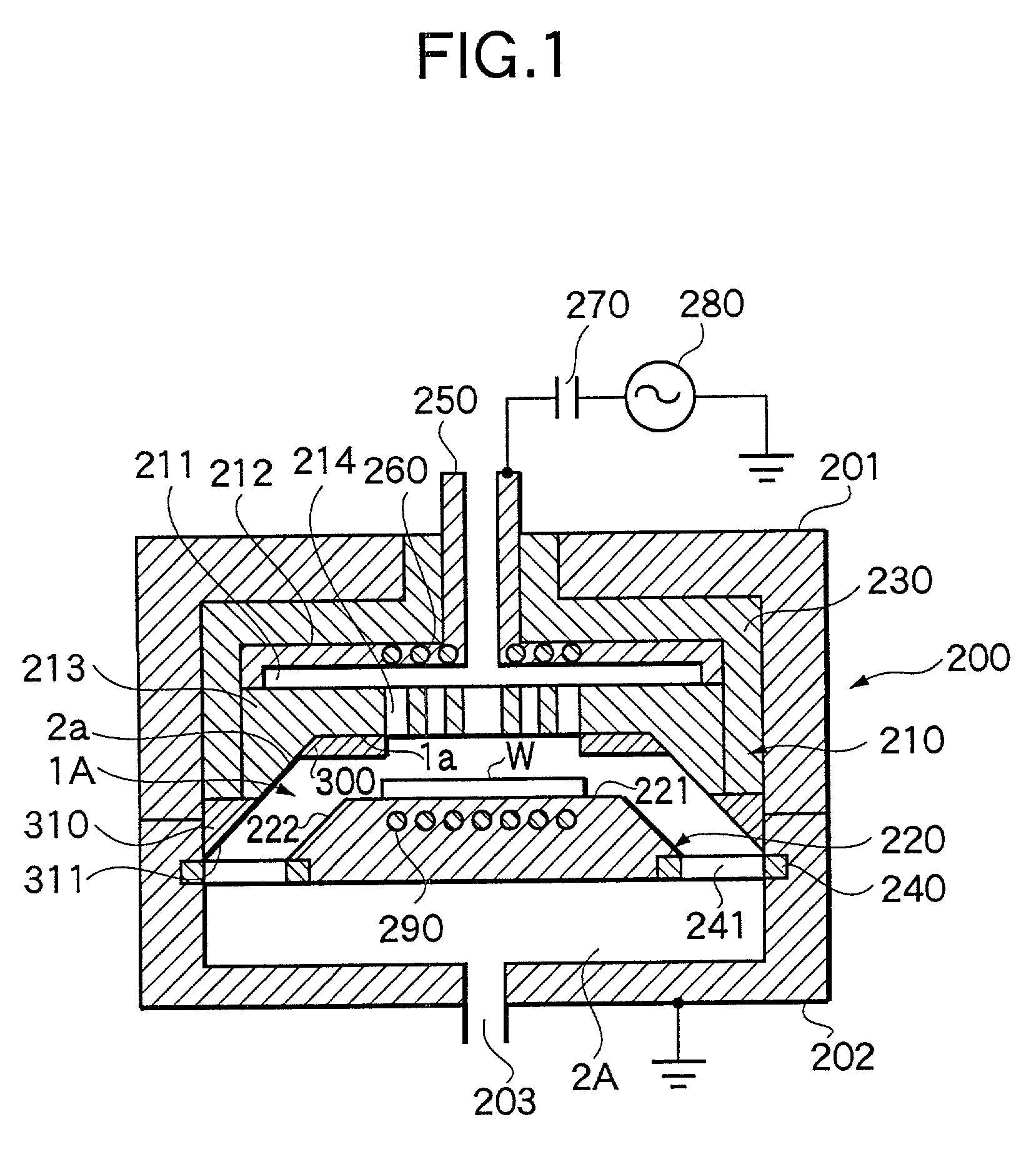
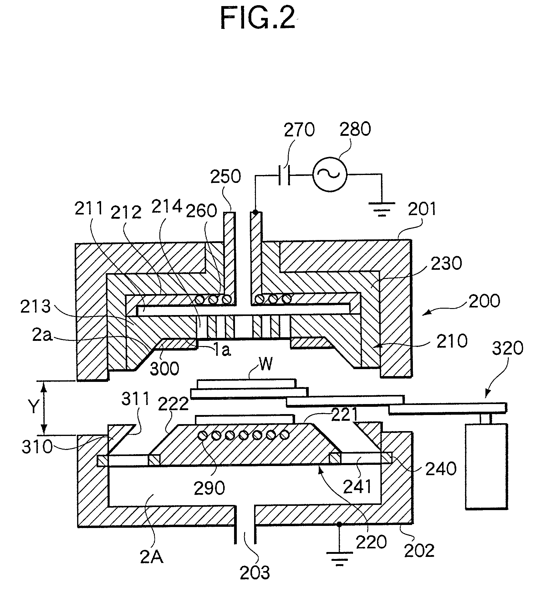
[0149] FIG. 6 is a lateral cross-sectional diagram illustrating a second embodiment of the plasma CVD device to which the present invention pertains. In FIG. 6 those parts which have more or less the same function as those in FIG. 1 are have been allocated the same codes, and a detailed description will be omitted.
[0150] It has been described how in the first embodiment it the discharge surface on the edge of the gas dispersion plate 213 is extended first horizontally and then at an angle in excess of 90 degrees to the horizontal section 1a, so as to become progressively broader as it proceeds downwards. In the present embodiment, as FIG. 6 shows, the discharge surface 61a on the edge of the gas dispersion plate 213 is instead extended so as to form a concave curved surface, thus ensuring that this discharge surface 61a becomes progressively broader as it proceeds downwards.
[0151] 2.2 Effects
[0152] This structure also makes it possible ...
third embodiment
[0156] 3. Third Embodiment
[0157] FIG. 8 is a lateral cross-sectional diagram illustrating a third embodiment of the plasma CVD device to which the present invention pertains.
[0158] In the examples described in the foregoing embodiments, the surface 311 of the insulator 310 which comes into contact with the gas comprises a single surface forming an angle in excess of 90E to the horizontal surface. In contrast to this, the surface 311 which comes into contact with the gas in the example illustrated in FIG. 8(a) constitutes a combination of two surfaces 81a, 82a which form angles in excess of 90 degrees to the horizontal surface and are inclined differently from each other. Meanwhile, in the example illustrated in FIG. 8(b) the surface 311 which comes into contact with the gas forms a single concave curved surface. Moreover, in the example illustrated in FIG. 8(c) the surface 311 which comes into contact with the gas constitutes a combination of a horizontal surface 101a and a vertical...
PUM
| Property | Measurement | Unit |
|---|---|---|
| Power | aaaaa | aaaaa |
| Adhesion strength | aaaaa | aaaaa |
| Area | aaaaa | aaaaa |
Abstract
Description
Claims
Application Information