System and method for three-dimensional reconstruction of a tubular organ

a three-dimensional reconstruction and tubular organ technology, applied in the field of medical imaging systems, can solve the problems of limited time, safety and cost, and the overall number of images that can be obtained is limited by time, safety and cost, and the estimation of stenosis severity is usually not accurate by either means

Inactive Publication Date: 2010-06-22
PAIEON INC
View PDF88 Cites 342 Cited by
  • Summary
  • Abstract
  • Description
  • Claims
  • Application Information

AI Technical Summary

Benefits of technology

[0021]Accordingly, embodiments of the present invention overcome the drawbacks and problems associated with the prior art systems, and present simple to use and straight forward systems and methods for accurately imaging and creating a 3DR of a tubular organ which may be used with conventional X-ray angiography systems. Specifically, some embodiments of the present invention present methods and systems for 3DR of a single vascular structure of interest, using two (and in some embodiments, more than two), 2D X-ray images.

Problems solved by technology

However, it is generally very difficult to obtain purely perpendicular perspectives of the vessels.
However, the overall number of images that can be obtained is limited by time, safety and cost.
As indicated above, since most of the images are, in general, not purely perpendicular to the arterial axis, estimation of stenosis severity is usually not accurate by either means.
However, cross-section area measurements are rarely addressed, although attempts have been made to achieve a precise representation of cross section profile along the vessels.
At the same time, this step is very sensitive and could easily produce incorrect measurements.
Other problems exist with reference to the methods for the existing 3D imaging systems.
Although bi-plane acquisition minimizes distortions due to cardiac cycle phase, the technique is insufficient in some situations of epi-polar geometry ambiguity.
With regard to rotational acquisition systems, although close in time, these systems do not solve either a cardiac phase problem or the epi-polar geometry ambiguity.
However, the confident and accurate identification of at least five corresponding points on multiple images is a burdensome procedure, if at all possible, since, for example, the right coronary artery system often lacks adequate branching points.
Moreover, whether non-linear or linear optimization is used, both solutions suffer from an instability problem.
However, it is very often the case that the precise location of a branching point is difficult to identify due to that area of the arterial tree overlapping another vessel or itself Moreover, as usual in computational geometry, not every required set of points is useful to produce the transformation.
Finally, transformation to 3DR from a family of perspective transformations, in general, can not compensate for local distortions in each image caused by the image being taken at different phase of either the heart cycle and patient respiration (for example).
However, this approach yields sufficient results only if.
This is why, in clinical practice, the restrictions of the straightforward epi-polar geometry approach are very limiting in tenns of accuracy and quality of the 3D model.
In view of the above-mentioned short comings of the prior art, current 2D QCA systems do not deliver sufficient support for coronary angiography (for example) and current 3D QCA systems are not in clinical use since these systems either deliver incorrect results or are too cumbersome to use.

Method used


Image

  • System and method for three-dimensional reconstruction of a tubular organ
  • System and method for three-dimensional reconstruction of a tubular organ
  • System and method for three-dimensional reconstruction of a tubular organ

Examples


Embodiment Construction

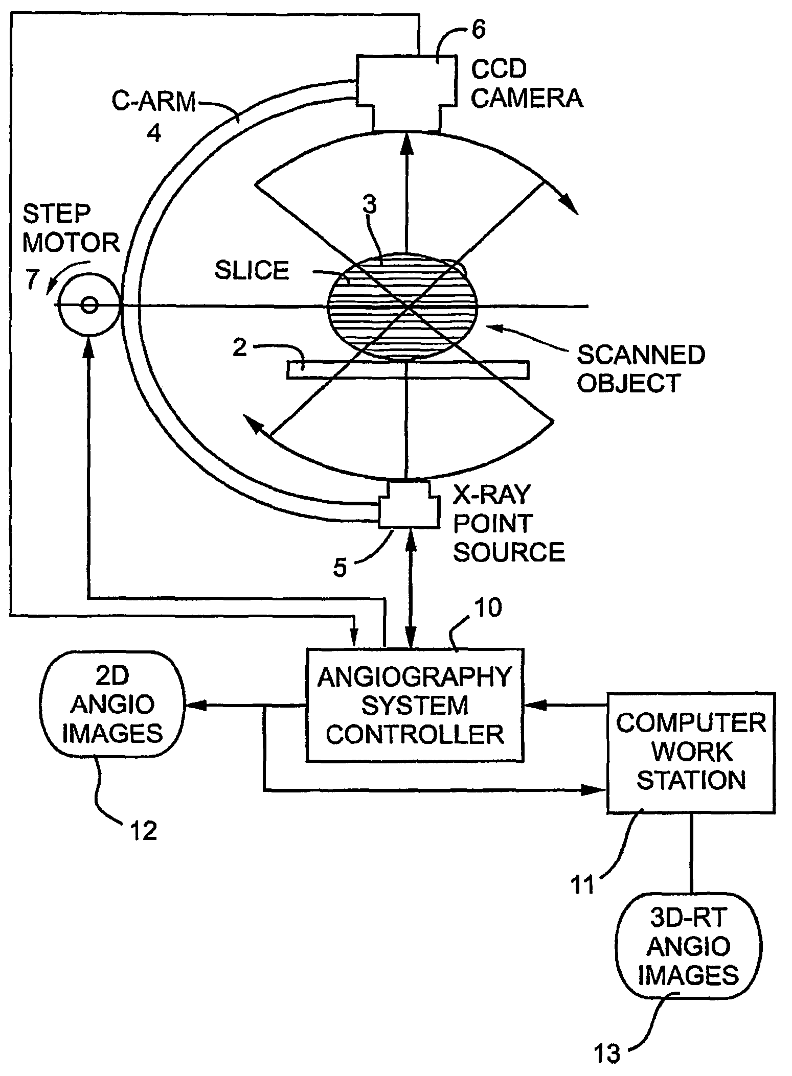
[0079]The embodiments of the present invention may be integrated into existing catheterization systems to produce both 2D and 3DR images. FIG. 1, for example, illustrates one exemplary system constructed in accordance with some embodiments of the present invention useful for producing either two-dimensional angiographs and / or 3DRs of a patient's vascular system. Such a system may include a horizontal support such as a table 2 for a patient 3 under examination, and a gantry C-arm 4 which encloses the patient's body. The C-arm supports a radiation source 5 at one side of the patient's body, and a radiation detector 6 at the opposite side and in alignment with the radiation source. The radiation source 5 may be an X-ray point source which produces, for example, a conical X-ray beam. The radiation detector, which may consist of a CCD camera having a plurality of radiation detector elements.

[0080]The apparatus may further include a step motor 7 for changing the angular position of the ra...


PUM


Abstract

Embodiments of the present invention include methods and systems for three-dimensional reconstruction of a tubular organ (for example, coronary artery) using a plurality of two-dimensional images. Some of the embodiments may include displaying a first image of a vascular network, receiving input for identifying on the first image a vessel of interest, tracing the edges of the vessel of interest including eliminating false edges of objects visually adjacent to the vessel of interest, determining substantially precise radius and densitometry values along the vessel, displaying at least a second image of the vascular network, receiving input for identifying on the second image the vessel of interest, tracing the edges of the vessel of interest in the second image, including eliminating false edges of objects visually adjacent to the vessel of interest, determining substantially precise radius and densitometry values along the vessel in the second image, determining a three dimensional reconstruction of the vessel of interest and determining fused area (cross-section) measurements along the vessel and computing and presenting quantitative measurements, including, but not limited to, true length, percent narrowing (diameter and area), and the like.

Description

CLAIMS TO PRIORITY AND RELATED APPLICATIONS[0001]The present application claims priority under 35 U.S.C. §119(e) of U.S. provisional patent application Nos. 60 / 505,430, filed Sep. 25, 2003, 60 / 506,178, filed Sep. 29, 2003, and 60 / 577,981, filed Jun. 7, 2004, each disclosure of which, in its entirety, is incorporated herein by reference.BACKGROUND OF THE INVENTION[0002]1. Field of the Invention[0003]The present invention relates to medical imaging systems, and more specifically to medical imaging systems for use in angiography, for example.[0004]2. Background of the Invention[0005]A stenosis in a blood vessel, for example, an artery refers to narrowing of the artery lumen due to plaque formation on the interior wall of the artery. The severity of the narrowing depends upon the amount of cross-sectional area of the lumen that is occluded by plaque. While narrowing of the arteries may occur in any artery of the body (e.g., carotid arteries), particular concern has been placed on invest...

Claims


Application Information

Patent Timeline
Patent Type & Authority Patents(United States)
IPC IPC(8): G06K9/00G06K9/36G06T7/00
CPCG06T7/0067G06T7/564
Inventor ZARKH, MICHAELKLAIMAN, MOSHE
Owner PAIEON INC
Why Eureka
Try Eureka