
Foldable Exterior Rearview Mirror For Motor Vehicle

Inactive Publication Date: 2008-10-16
TSENG MILO
View PDF13 Cites 25 Cited by
  • Summary
  • Abstract
  • Description
  • Claims
  • Application Information

AI Technical Summary

Benefits of technology

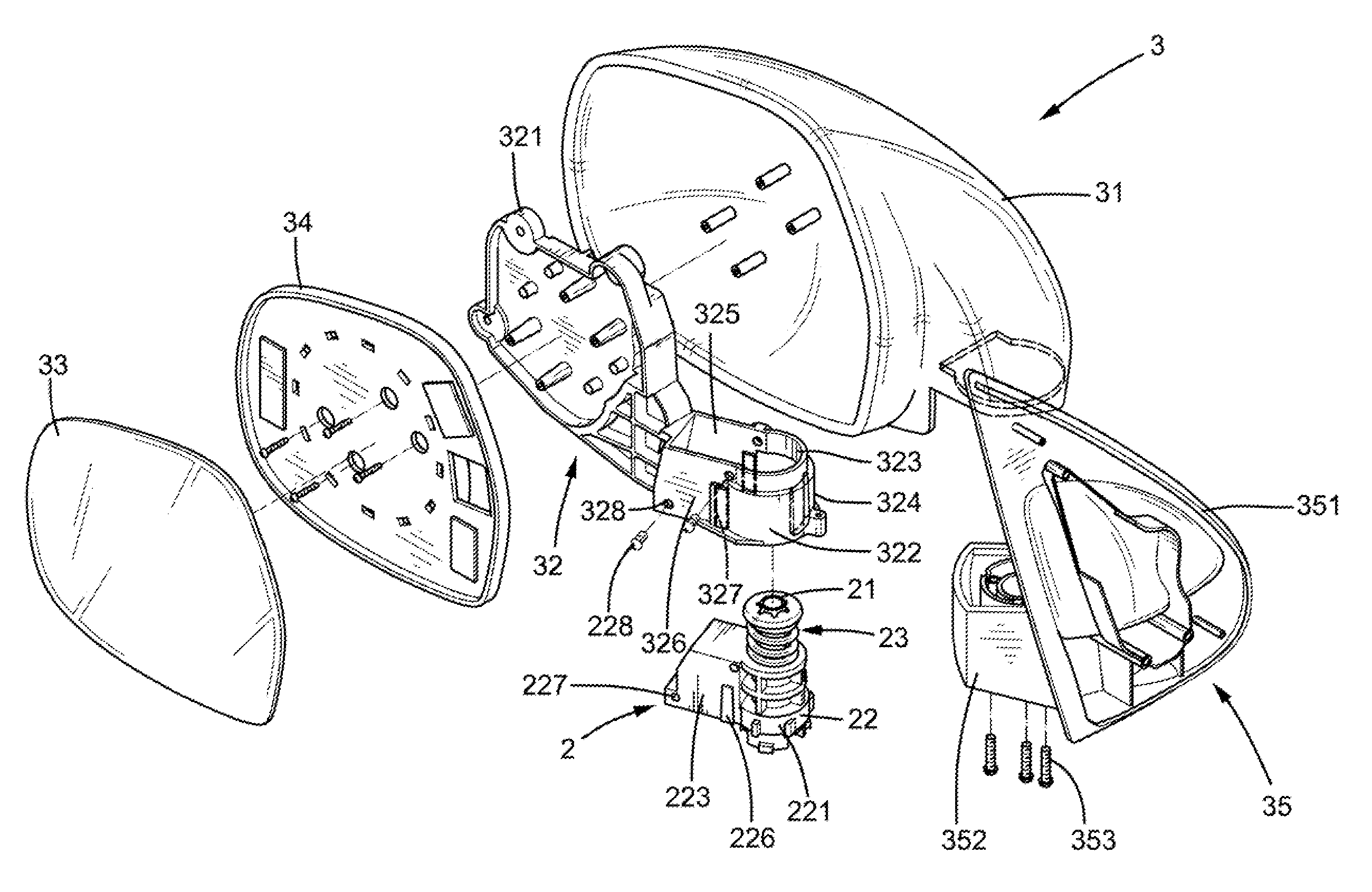
[0005]The present invention solves this need and other problems in the field of exterior rearview mirrors of motor vehicles by providing, in a preferred form, a housing, a bracket adapted to be fixed to a side of a motor vehicle, and a connecting arm mounted in the housing and including a sleeve portion suitable for receiving a manual adjusting device or an electric adjusting device. A mirror is adapted to be mounted to the connecting arm. The manual adjusting device includes a pivot shaft and a support frame. The pivot axle includes an axle and a base fixed to a lower end of the axle. The base is mounted to the bracket. The support frame includes a cylindrical portion and a coupling portion extending outward from a periphery of the cylindrical portion. The cylindrical portion and the coupling portion of the support frame are removably engaged in the sleeve portion of the connecting arm. The cylindrical portion of the support frame is rotatably mounted around the axle and includes an annular compartment in a bottom face thereof. The base of the pivot shaft is rotatably received in the annular compartment of the cylindrical portion of the support frame. A user may select the manual adjusting device or the electric adjusting device to be mounted in the sleeve portion of the connecting arm. This allows the user to easily and rapidly convert a manual foldable exterior rearview mirror into or from an electric exterior rearview mirror without the need of replacing the connecting arm.
[0006]In the most preferred form, the base includes a top face having a plurality of annularly spaced first positioning holes and a plurality of annularly spaced second positioning holes. An end wall defining the annular compartment of the support frame includes a plurality of positioning grooves. A positioning mechanism is provided for positioning the support frame relative to the pivot shaft and includes a plurality of balls; a spring mounted around an upper portion of the axle that extends beyond the cylindrical portion of the support frame; and a positioning ring mounted on top of the axle. The spring is attached between the positioning ring and a top face of the cylindrical portion of the support frame to bias the cylindrical portion of the support frame toward the base. Each ball has an upper portion received in one of the positioning grooves of the support frame and a lower portion selectively received in one of the first positioning holes or one of the second positioning holes. The sleeve portion of the connecting arm includes an annular section and a frame section. The annular section includes a cylindrical hole for receiving the cylindrical portion of the support frame. The frame section includes a coupling hole for receiving the coupling portion of the support frame. The frame section of the sleeve portion of the connecting arm includes two engaging grooves respectively in two opposite lateral walls thereof. The coupling portion of the support frame includes two projections respectively on two opposite walls thereof and slidably received in the engaging grooves of the frame section of the sleeve portion of the connecting arm. Screws are extended through holes in the frame section of the sleeve portion of the connecting arm and holes in the coupling portion of the support frame for securely fixing the coupling portion of the support frame in the frame section of the sleeve portion of the connecting arm.

Problems solved by technology

Specifically, the adjusting device of an electric foldable exterior rearview mirror requires a motor and a speed reducer such that the structure and the outline of the adjusting device of the electric foldable exterior rearview mirror are significantly different from those of a manual foldable exterior rearview mirror and, thus, can not allow simple replacement therebetween.
In a case that a user wishes to convert the foldable exterior rearview mirror from one type into the other, the procedure is inconvenient, time-consuming, and costly, for both the adjusting device and the connecting arm must be replaced.
The manufacturers must produce various types of adjusting devices and connecting arms for both the electric foldable exterior rearview mirrors and manual foldable exterior rearview mirrors, which also increases the costs.

Method used


Image

  • Foldable Exterior Rearview Mirror For Motor Vehicle
  • Foldable Exterior Rearview Mirror For Motor Vehicle
  • Foldable Exterior Rearview Mirror For Motor Vehicle

Examples


Embodiment Construction

[0019]A manual foldable rearview mirror for a motor vehicle according to the preferred teachings of the present invention is shown in the drawings and generally designated 3. The manual foldable rearview 3 includes a housing 31, a connecting arm 32 mounted in the housing 31, a mirror frame 34 to which a mirror 33 is mounted, a bracket 35, and a manually operable adjusting device 2. The connecting arm 32 includes a mirror frame mounting portion 321 to which the mirror frame 34 is mounted. A sleeve portion 322 extends from a side of the mirror frame mounting portion 321. The sleeve portion 322 includes an annular section 324 defining a cylindrical hole 323 and a frame section 326 defining a coupling hole 325 that is in communication with the cylindrical hole 323. In the most preferred from shown, the frame section 326 includes two engaging grooves 327 respectively in two opposite lateral walls thereof and extending vertically.

[0020]According to the preferred form, the bracket 35 inclu...


PUM


Abstract

A foldable exterior rearview mirror includes a housing, a bracket fixed to a side of a motor vehicle, and a connecting arm mounted in the housing and including a sleeve portion suitable for receiving an electric adjusting device or manual adjusting device. The manual adjusting device includes a pivot shaft and a support frame. The pivot axle includes an axle and a base fixed to a lower end of the axle. The base is mounted to the bracket. The support frame includes a cylindrical portion and a coupling portion extending outward from a periphery of the cylindrical portion. The cylindrical portion and the coupling portion of the support frame are removable engaged in the sleeve portion of the connecting arm. A user may select the manual adjusting device or the electric adjusting device to be mounted in the sleeve portion of the connecting arm.

Description

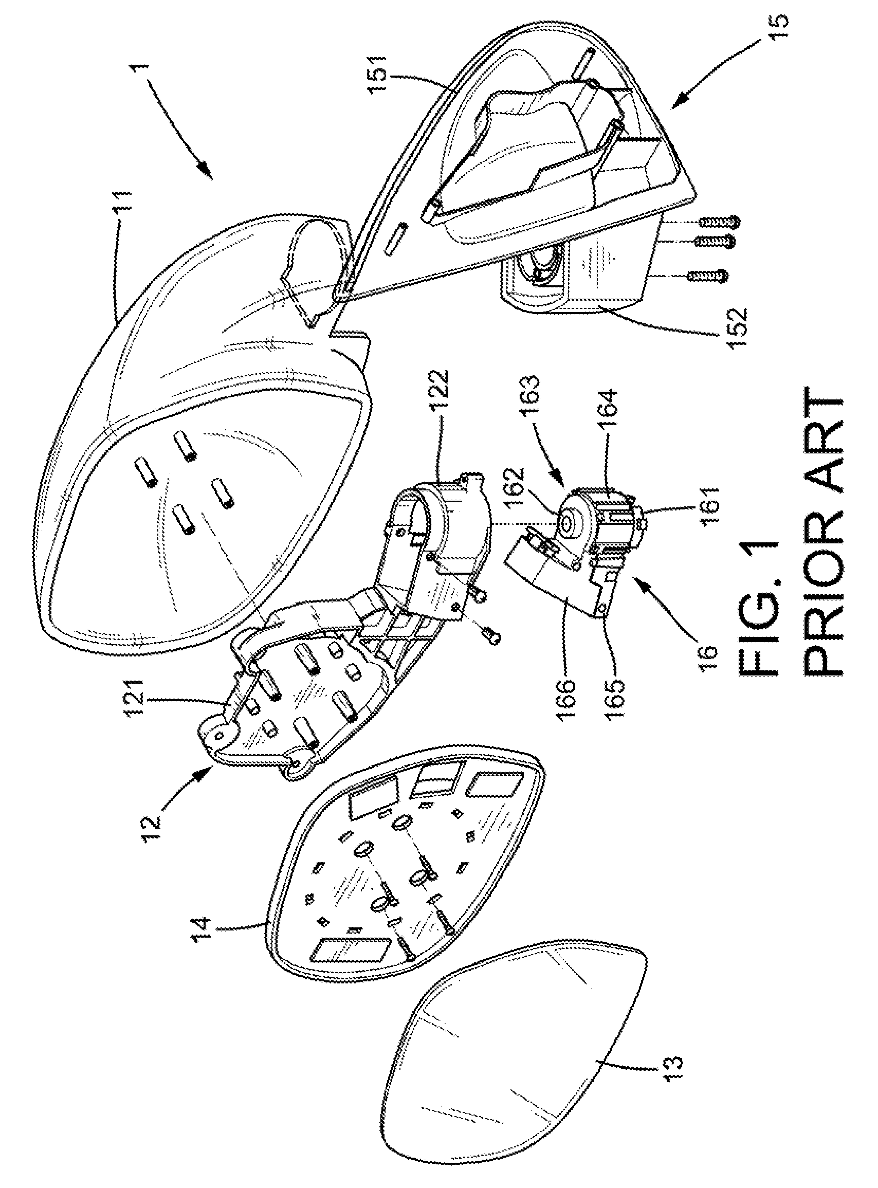
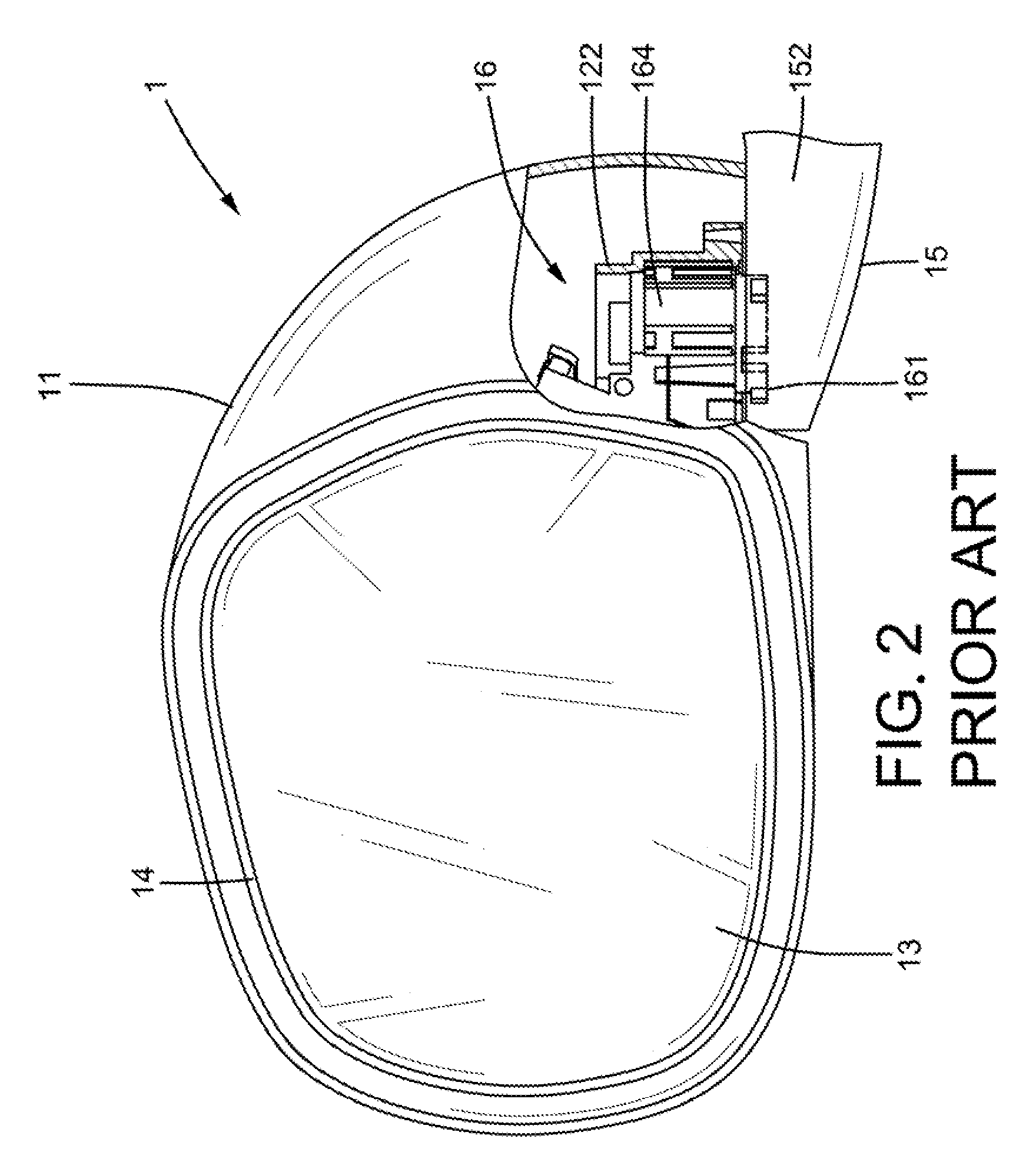
BACKGROUND OF THE INVENTION [0001]The present invention relates to a foldable exterior rearview mirror for a motor vehicle. More particularly, the present invention relates to a manual foldable exterior rearview mirror that can be easily converted into or from an electric foldable exterior rearview mirror.[0002]Exterior rearview mirrors are useful for motor vehicles during passing and turning. The exterior rearview mirrors protruding from the vehicle sides can be designed to be foldable to avoid damage during parking. FIGS. 1 and 2 illustrate a conventional electric foldable exterior rearview mirror 1 including a housing 11, a connecting arm 12 mounted in the housing 11, a mirror frame 14 mounted in the housing 11, a bracket 15, and electric adjusting device 16, and a mirror 13 mounted to the mirror frame 14. The connecting arm 12 includes a mirror frame mounting portion 121 to which the mirror frame 14 is mounted. A sleeve portion 122 extends from a side of the mirror frame mountin...

Claims


Application Information

Patent Timeline
IPC IPC(8): G02B7/182
CPCB60R1/0617B60R1/074
Inventor TSENG, MILO
Owner TSENG MILO
Learn More