Cooling plate for the temperature control of at least one battery cell and a battery system

a battery cell and cooling plate technology, applied in the direction of cell components, electrochemical generators, lighting and heating apparatus, etc., can solve the problems of unreliable temperature control of traction battery cells, and achieve the effects of improving the cooling plate, good heat transfer, and durable sealing of the flow ducts

Active Publication Date: 2022-06-07
ROBERT BOSCH GMBH
View PDF12 Cites 0 Cited by
  • Summary
  • Abstract
  • Description
  • Claims
  • Application Information

AI Technical Summary

Benefits of technology

[0003]The present invention describes a cooling plate for the temperature control of at least one battery cell, especially for a traction battery. The cooling plate comprises a frame with flow ducts designed for the flowing of a coolant through them and a flexibly configured cover. The flexibly configured cover bounds the flow ducts in fluid-tight manner and is provided for the thermal contacting of the at least one battery cell. According to the invention, the flow ducts comprise at least one perturbing contour, which is provided to increase the turbulence in the coolant flowing through the flow ducts. This has the benefit of improved cooling performance or temperature control ability as compared to the prior art. The increased turbulence which can be produced by means of the perturbing contours serves for more intense mixing of the coolant. In particular, a laminar flow formed by the coolant within the flow ducts, especially a laminar flow formed along a longitudinal direction of the flow ducts, is disrupted such that a temperature gradient perpendicular to the longitudinal direction is minimized. The perturbing contour produces for example a turbulent flow with eddy currents in the coolant. Preferably, the perturbing contour produces for example a flow with a Reynolds number over 100, preferably over 1000, especially preferably over 2000.
[0004]The cooling plate preferably comprises a first port, which is provided for a supply of the coolant. The cooling plate preferably comprises a second port, which is provided for a drainage or an outflow of the coolant. Especially preferably, the frame comprises the first port. Especially preferably, the frame comprises the second port. This has the benefit that the cooling plate is especially reliable and robust, especially being leakproof or tight.

Problems solved by technology

Such cooling plates have the drawback that a reliable temperature control of the traction battery cells is not always possible.

Method used


Image

  • Cooling plate for the temperature control of at least one battery cell and a battery system
  • Cooling plate for the temperature control of at least one battery cell and a battery system
  • Cooling plate for the temperature control of at least one battery cell and a battery system

Examples


Embodiment Construction

[0032]In the various variant embodiments, the same parts are given the same reference numbers.

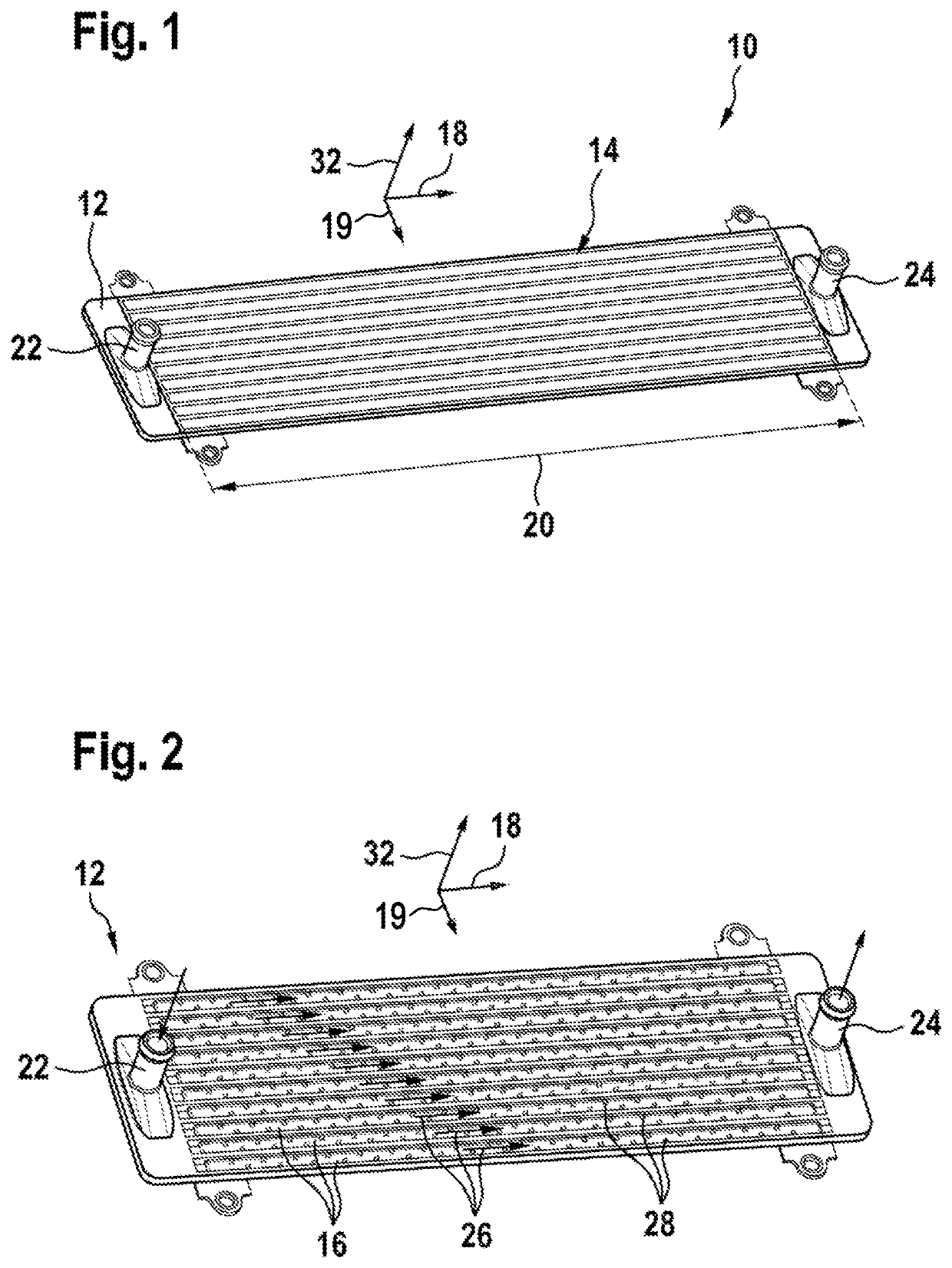
[0033]FIG. 1 shows in a perspective view one embodiment of a cooling plate 10 according to the invention for the temperature control of at least one battery cell.

[0034]The cooling plate 10 comprises a frame 12. The frame in the exemplary embodiment shown in FIG. 1 is made of plastic. The cooling plate 10 comprises a flexibly configured cover 14. The frame 12 comprises flow ducts 16. The flow ducts 16 are covered or closed off by the flexibly configured cover 14. In particular, the flow ducts 16 are closed off by the flexibly configured cover 14 from the outer surroundings.

[0035]FIG. 2 shows a perspective view of the frame 12 without the flexibly configured cover 14 in order to reveal the flow ducts 16. The flow ducts 16 are oriented each time along a longitudinal direction 18. In the exemplary embodiment shown in FIG. 2, the frame 12 comprises for example ten flow ducts 16. The flow ducts 1...


PUM

PropertyMeasurementUnit
angleaaaaaaaaaa
Reynolds numberaaaaaaaaaa

Abstract

A cooling plate (10) for the temperature control of at least one battery cell, especially for a traction battery, comprising a frame (12) with flow ducts (16) designed for the flowing of a coolant through them and a flexibly configured cover (14), which bounds the flow ducts (16) in fluid-tight manner and is provided for the thermal contacting of the at least one battery cell. It is proposed that the flow ducts (16) comprise at least one perturbing contour (28), which is provided to increase the turbulence in the coolant flowing through the flow ducts (16).

Description

BACKGROUND OF THE INVENTION[0001]The invention relates to a cooling plate for the temperature control of at least one battery cell. Furthermore, the invention also relates to a battery system with such a cooling plate.[0002]Cooling plates are known from EP0516280A1 for the temperature control of traction battery cells, having flow ducts covered by a flexible cover for the thermal contacting of the traction battery. Such cooling plates have the drawback that a reliable temperature control of the traction battery cells is not always possible.SUMMARY OF THE INVENTION[0003]The present invention describes a cooling plate for the temperature control of at least one battery cell, especially for a traction battery. The cooling plate comprises a frame with flow ducts designed for the flowing of a coolant through them and a flexibly configured cover. The flexibly configured cover bounds the flow ducts in fluid-tight manner and is provided for the thermal contacting of the at least one battery...

Claims


Application Information

Patent Timeline
Patent Type & Authority Patents(United States)
IPC IPC(8): H01M10/6556F28D21/00F28F3/04H01M10/613
CPCH01M10/6556H01M10/613H01M10/6554H01M10/6567H01M50/20H01M10/625F28F3/044F28F3/12F28F13/12F28F2255/02F28D2021/0029F28D1/03Y02E60/10
Inventor SCHMITT, MARKUSRUEHLE, ANDREASKOPP, BENJAMIN
Owner ROBERT BOSCH GMBH
Why Eureka
Try Eureka