Punching system

a technology of punching system and punching plate, which is applied in the direction of electrographic process, manufacturing tools, instruments, etc., can solve the problems of wasting power of the punching system, and affecting the effect of forming imag

Inactive Publication Date: 2001-12-13
FUJIFILM BUSINESS INNOVATION CORP
View PDF0 Cites 34 Cited by
  • Summary
  • Abstract
  • Description
  • Claims
  • Application Information

AI Technical Summary

Benefits of technology

[0010] The invention has been made in view of the above circumstances, and therefore a first object of the invention is to provide a punching system that can not only always punch holes in the centers of sheet materials of recording paper, etc., different in size, but also prevent wasting power because a punching mechanism is not moved unnecessarily for recording paper, etc., which need not be punched and prevent start of the image formation operation from being delayed by time required for moving the punching mechanism.
[0011] A second object of the invention is to provide a punching system that can prevent recording paper, etc., of a long width direction size from being caught in the coupling part of punch and die sections and a paper jam from occurring without upsizing the punching system.
[0012] A third object of the invention is to provide a punching system that can detect a width direction end position of recording paper with good accuracy and punch holes in predetermined positions of recording paper with good accuracy even if simple means is used as means for sensing a width direction end position of recording paper.
[0013] A fourth object of the invention is to provide a punching system that can prevent skew from causing punch hole position accuracy to be worsened if recording paper is skewed.

Problems solved by technology

However, the prior arts involve the following problems: In Japanese Patent Laid-Open Nose.
Thus, for recording paper which need not be punched, the paper center detection means may also detect the width direction center of paper based on detection information of the width direction end position of paper and move the punching mechanism so as to match the width direction center of paper with the arrangement center of the punching edges before punching; it is feared that electric power of the image formation system may be wasted or that starting the image formation operation may be delayed by the time required for moving the punching mechanism.
When the punching mechanism of the punching system is moved in response to the width direction size of the recording paper, if the punching section containing the punching edges and the die section are moved separately, it is feared that they may be placed out of position and the punching edges may come in contact with the dies, breaking the punching edges.
By the way, in the punching system, if recording paper of a long width direction size which need not be punched is transported after recording paper of a short width direction size Is punched, the end of the recording paper of a long width direction size is caught in the coupling part of the punch and die sections, causing a paper jam to occur.
To circumvent this problem, if the coupling part of the punch and die sections is widened to a position where the coupling part is not caught in the recording paper of a long width direction size, the punching system is upsized, causing a new problem.
Hei 3-92299 uses a plurality of light emitting parts and light receiving parts placed facing each other for each of sheets different in width direction size as the detection means for detecting the width direction end position of paper, thus the detection means configuration becomes complicated and expensive, resulting in an increase in cost.
Further, the punching system does not take any steps for a sheet skewed with respect to the recording paper transport direction and also involves a problem of worsening the punch position accuracy because of the skewed sheet.

Method used


Image

  • Punching system
  • Punching system
  • Punching system

Examples


embodiment 1

[0080]

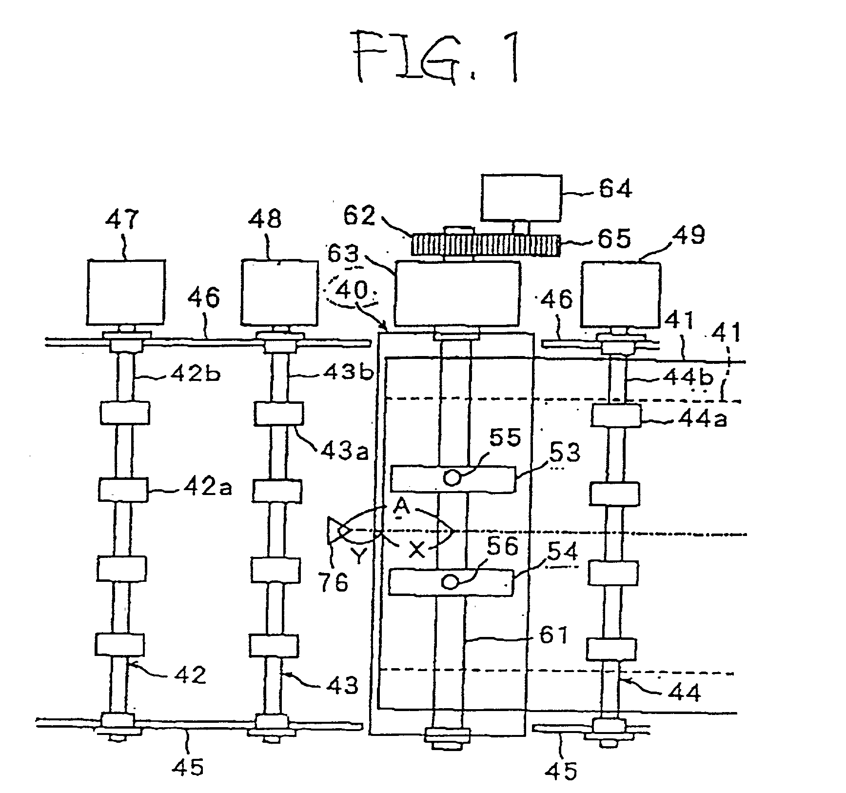
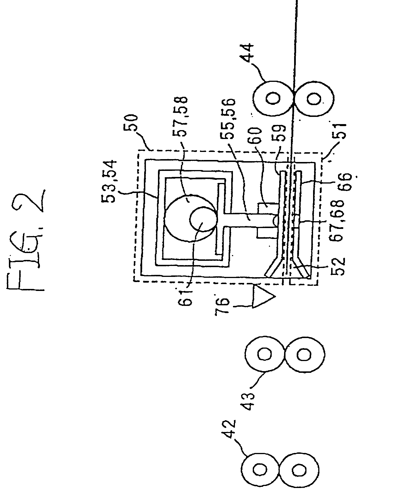
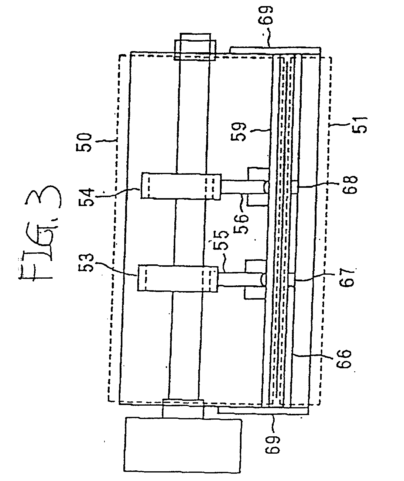
[0081] By the way, a punching system according to a first embodiment of the invention. is used in combination with a digital color image formation system configured as described above, for example, to punch holes in a sheet material of recording paper, etc., on which a color image is formed. For example, the punching system is attached to the outside of a discharge section of a digital color image formation system as one of postprocessing units in place of the discharge tray 36, but may be integrally built In the digital color image formation system, of course.

[0082] To punch holes for each sheet by the punching system, the variations in the width direction positions of the sheets and skew thereof cause punch hole position accuracy to be worsened. Different setting of recording paper 24 on the paper feed cassettes 28, 29, and 30, eccentricity of the transport roll 32, slipping of a sheet of recording paper 24, etc., with respect to the transport roll 32, or the like is possibl...

embodiment 2

[0109]

[0110] FIGS. 12 and 13 show a punching system according to a second embodiment of the invention. Parts identical with or similar to those of the first embodiment previously described are denoted by the same reference numerals. The punching system according to the second embodiment is applied to an image formation system of a so-called "side registration" system for forming an image with one axial end of a photosensitive drum 20 as the reference and transporting a sheet 41 of recording paper, etc., with one end of the width direction thereof as the reference for forming an image on the sheet, and moreover is applied to a system with small variations in the width direction positions of the sheets 41 and small skew thereof. With the punching system, the center line position in the width direction of each sheet 41 varies depending on the size of sheet 41, thus the middle of punching edges 55 and 56 needs to be aligned with the center line of a sheet 41 of each size before the shee...

embodiment 3

[0129]

[0130] FIGS. 17 and 18 show a punching system according to a third embodiment of the invention. Parts identical with or similar to those of the embodiment previously described are denoted by the same reference numerals. The punching system according to the third embodiment is applied to an image formation system of a so-called "side registration" system for forming an image with one axial end of a photosensitive drum 20 as the reference and transporting a sheet 41 of recording paper, etc., with one end in the width direction thereof as the reference for forming an image on the sheet, and moreover is applied, to a system with large variations in the width direction positions of the sheets 41 and small skew thereof. With the punching system, the center line position in the width direction of each sheet 41 varies depending on the size of sheet 41 and the variations in the width direction positions of sheets 41, thus the middle of punching edges 55 and 56 needs to be aligned with ...


PUM

PropertyMeasurementUnit
distanceaaaaaaaaaa
widthaaaaaaaaaa
sizeaaaaaaaaaa

Abstract

A punching mechanism has a plurality of predetermined standby positions where the punching mechanism is previously moved by move means and stands by based on size information in the width direction of a sheet material and punching execution information as to whether or not the sheet material is to be punched. The standby position corresponding to a sheet material of the maximum width that can be punched by the punching mechanism and the standby position applied when punching is not executed are set to substantially the same position.

Description

BACKGROUND OF THE INVENTION[0001] 1. Field of the Invention[0002] This invention relates to a punching system used in combination with an image formation system such as an electrophotographic copier or a printer for automatically making holes in a sheet material of recording paper, etc., to or on which an image is copied or recorded.[0003] 2. Description of the Related Art[0004] Hitherto, punching systems used in combination with an image formation system such as an electrophotographic copier or a printer have already been proposed as disclosed in Japanese Patent Laid-Open No. Hei 3-92299, Hei 5-162919, etc., for example. An image formation system according to Japanese Patent Laid-Open No. Hei 3-92299 has a punching mechanism comprising a plurality of punching edges movable with respect to a paper transport passage, the punching edges being placed side by side in a predetermined spacing in a width direction of recording paper, characterized by paper center detection means for detect...

Claims


Application Information

Patent Timeline
Patent Type & Authority Applications(United States)
IPC IPC(8): B26D5/34B26D7/26B26F1/02B26F1/10
CPCB26D5/007B26D5/34B26D7/2628B26F1/02B26F1/10G03G2215/00818Y10T83/8843Y10T83/178Y10T83/8841Y10T83/446Y10T83/541Y10T83/4795Y10T83/538Y10T83/9387
Inventor TAKAISHI, YOSHIYUKISATOU, RYUICHI
Owner FUJIFILM BUSINESS INNOVATION CORP
Why Eureka
Try Eureka