Camera system

a camera and system technology, applied in the field of cameras, can solve the problems of delay in transfer, camera head may not be able to withstand heat produced, etc., and achieve the effect of reducing the load on the optical uni

Inactive Publication Date: 2009-11-17
FUJIFILM HLDG CORP +1
View PDF6 Cites 10 Cited by
  • Summary
  • Abstract
  • Description
  • Claims
  • Application Information

AI Technical Summary

Benefits of technology

[0012]With this configuration, the camera system can avoid unnecessary consumption of power for data format conversion, thus preventing a waste of power.
[0014]With this configuration, the camera system can reduce unnecessary consumption of power for the data format conversion.
[0018]With this configuration, the camera system can avoid the optical unit from undergoing a load of power beyond capacity of the optical unit and also from malfunctioning, even when the optical unit has a low level of limits of power consumption.
[0020]The still picture shooting mode causes relatively little load of power required for the optical unit to perform shooting. It is therefore desirable that the camera system achieve a data format of image data to be received by the camera body, with which data format subsequent processing is easily performed, rather than that the load of power on the optical unit be reduced. In this respect, in the still picture shooting mode, the camera system having this configuration operates so that the optical unit converts image data into highly compatible, easy-to-process YC data and then transfers the YC data to the camera body. Accordingly, the camera system performs the processing suitable for the still picture shooting mode.
[0022]The continuous still picture shooting mode causes a heavy load of power required for the shooting section to perform shooting and therefore, when the data format conversion is additionally assigned to the optical unit, the load may exceed the capacity of the optical unit. In this regard, in the continuous still picture shooting mode, the camera system having this configuration operates so that the optical unit transfers image data in the form of simply digitized RAW data to the camera body and the camera body performs subsequent necessary processing on the data. Accordingly, the camera system can reduce the load on the optical unit.

Problems solved by technology

The camera system capable of selecting the shooting mode may require too long a time to transfer image data, if in a form of RAW data, from the camera head to the camera body, thus causing a delay in the transfer.
Moreover, the camera head may be unable to withstand heat produced incident to power consumption required for the camera head to convert a data format of the image data into a recording format.

Method used


Image

  • Camera system
  • Camera system
  • Camera system

Examples


Embodiment Construction

[0030]An embodiment of the present invention will be described below.

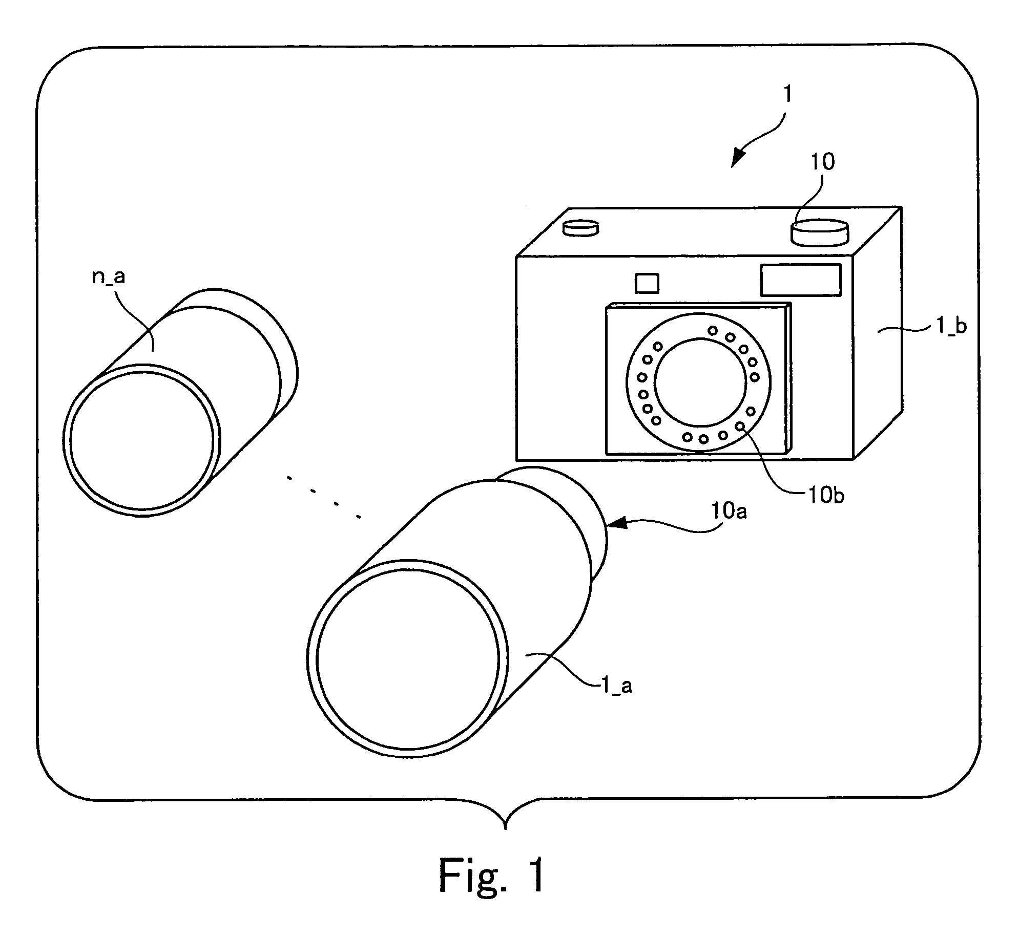
[0031]FIG. 1 is an exploded view of a camera system to which an embodiment of the present invention is applied.

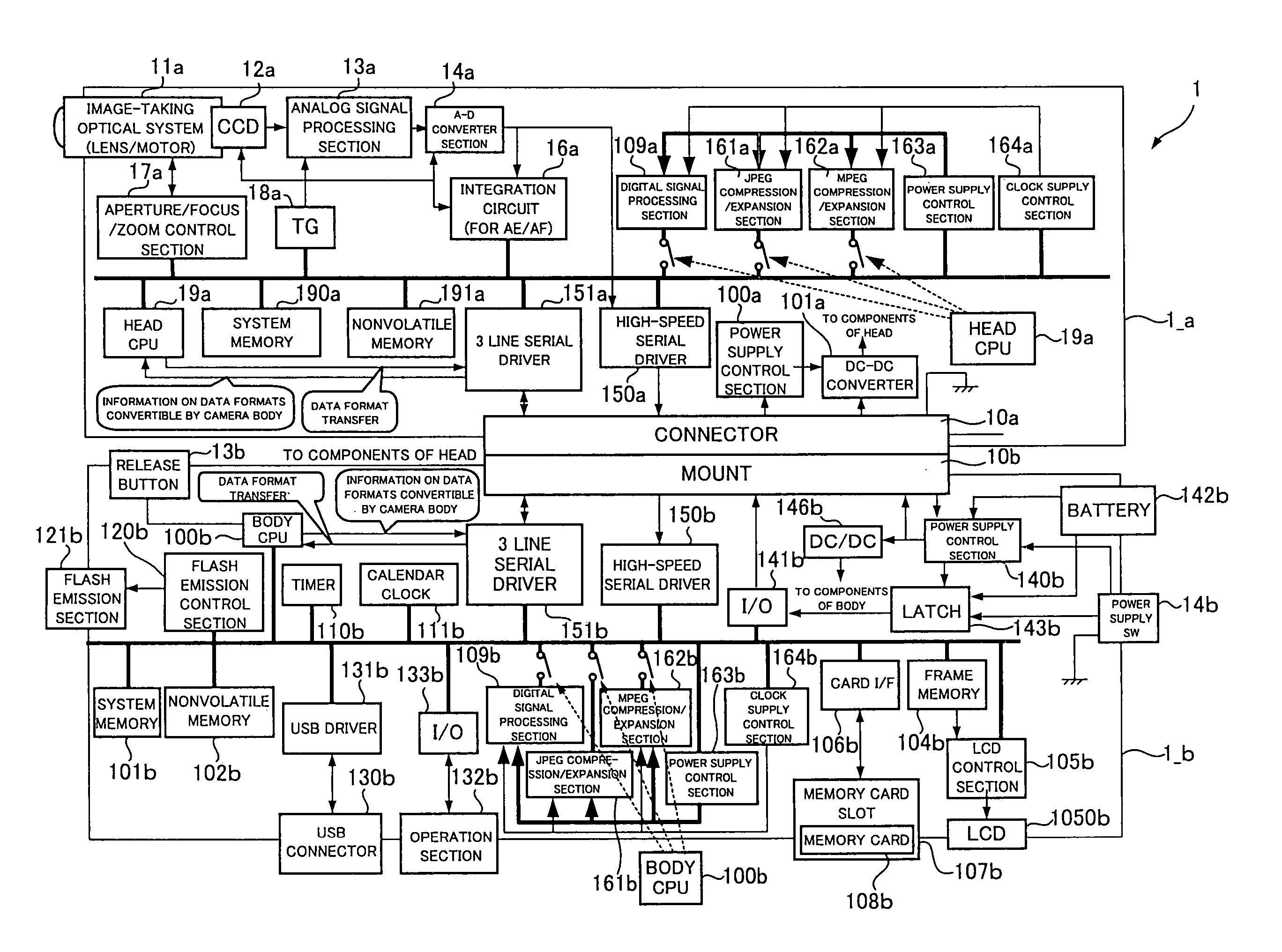
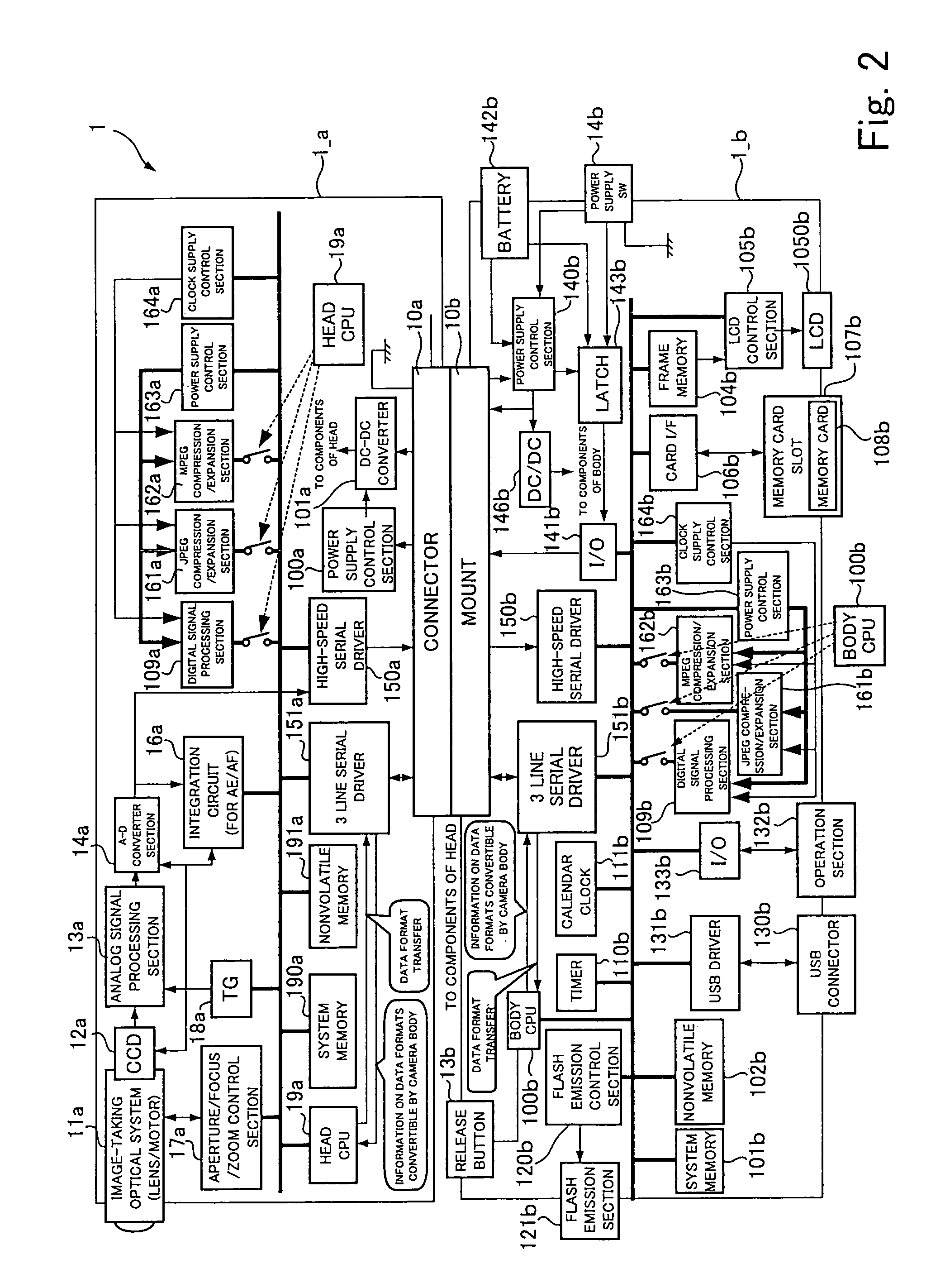
[0032]Plural types of camera heads 1—a, 2—a, . . . , and n_a, each of which has a taking lens and a CCD (charge coupled device) built-in, are provided for a camera system 1 shown in FIG. 1. Any one of the plural types of camera heads is selected for use. Each of the camera heads 1—a, 2—a, . . . , and n_a corresponds to one example of an optical unit according to the present invention. Firstly, a description will be given below taking an instance where the camera head 1—a is selected from among the plural types of camera heads 1—a, 2—a, . . . , and n_a.

[0033]The camera system 1 is configured of the camera head 1—a, and a camera body 1—b to which the camera head 1—a is detachably attached. The camera head 1—a and the camera body 1—b communicate each other through electrical contacts provided between a mount ...


PUM


Abstract

A camera system has an optical unit including: an optical system forming subject light into an image; a shooting section receiving the subject light formed into the image through the optical system, taking the image in a shooting mode selected from plural types of shooting modes, and generating an analog image signal indicating the subject light; and a data converter section converting the image signal into digital data having a data format corresponding to the shooting mode. The system also has a camera body including: a connect section where the optical unit is detachably attached; an image processing section obtaining the image data from the optical unit and processing the image data depending on the data format of the image data; and a mode selector section instructing the shooting section to select among the shooting modes and allowing the shooting section to perform shooting in the selected shooting mode.

Description

BACKGROUND OF THE INVENTION[0001]1. Field of the Invention[0002]The present invention relates to a camera system including an optical unit equipped with an image-taking optical system which forms subject light into an image, and a camera body to which the optical unit is detachably attached.[0003]2. Description of the Related Art[0004]There has been heretofore known a digital camera with interchangeable lenses, a camera system of which is configured of an interchangeable lens unit with a built-in taking lens, and a camera body with a built-in image pickup device, having the lens unit attached thereto. The digital camera with interchangeable lenses has an advantage of permitting users to select a lens unit suitable for use from among the lens units according to what purpose the users do shooting for.[0005]Recently, the digital camera with interchangeable lenses has undergone evolutionary development into a digital camera with interchangeable heads, in which a lens unit with an image ...

Claims


Application Information

Patent Timeline
Patent Type & Authority Patents(United States)
IPC IPC(8): H04N9/73H04N5/225H04N5/235H04N5/76
CPCH04N5/232H04N5/23209H04N5/23245H04N5/772H04N9/8047H04N5/907H04N9/7921H04N9/8042H04N23/663H04N23/55H04N23/651H04N23/667
Inventor TAKAHASHI, KEIICHIROTANAKA, HIROSHI
Owner FUJIFILM HLDG CORP
Why Eureka
Try Eureka