Printing apparatus

a printing machine and printing technology, applied in the field of printing machines, can solve the problems of prolonging the time of paper transport, changing the page sequence, and unable to change the order of pages, so as to prolong the life of the fixing assembly, reduce the duration of the rotation of the fixing roller, and optimize the printing sequence

Inactive Publication Date: 2005-04-26
CANON KK
View PDF13 Cites 10 Cited by
  • Summary
  • Abstract
  • Description
  • Claims
  • Application Information

AI Technical Summary

Benefits of technology

[0034]The printing apparatus in accordance with the present invention introduces the print reservation instruction. Thus, it can check a subsequent reservation state at the end of the printing of the first side, and optimize the print sequence. Therefore it can reduce the duration of the high voltage output, the duration of the high temperature of the heater, and the duration of the rotation of the photoconductive drum and that of the fixing pressurizing rollers. In addition, it enables the photoconductive drum and fixing pressurizing rollers to be rotationally driven individually. Thus, it can lengthen the duration of halting the output of the high voltage, the duration of halting the rotation of the photoconductive drum, and the duration of keeping the heater off and the duration of halting the rotation of the fixing pressurizing rollers during the double side transport.
[0035]As a result, the printing apparatus can prolong the life of the fixing assembly because of reduction in the duration of the rotation of the fixing rollers. In addition, it can prolong the life of the electrophotographic photoconductive body because of the reduction in the duration of applying the high voltage and the duration of the rotation of the photoconductive drum. Furthermore, it can decrease the power consumption because of the reduction in the duration of the high voltage output, the duration of the high temperature of the heater, and the duration of the rotation of the photoconductive drum and that of the fixing pressurizing rollers.

Problems solved by technology

However, when the printer has a small memory capacity, it can store only a small number of pages of the print information, thereby being unable to change page sequence.
Furthermore, as for the double-sided printing of reading data by a document reader to make double-sided copy, since it is performed with reading the data by the document reader, it cannot change the order of pages.
The method of printing the first side, reversing the sheet of paper to refeed it and printing its second side, and hence leaving only a sheet of paper on the passage of the paper reverse mechanism and paper refeed mechanism has a problem of prolonging the paper transport duration because of reversing the paper and refeeding it.
However, the transport speed of the recording medium is rapidly increasing with the speedup of the printer, thereby sharply shortening the time period of printing the first side, and reversing the sheet of paper to refeed it.
Accordingly, the method of printing the first side, reversing the sheet of paper to refeed it and printing its second side, and hence leaving only one sheet of paper on the passage of the paper reverse mechanism and paper refeed mechanism comes to have the following problems.
It cannot halt the electrophotographic charge generation during the time from the paper reversal to the refeed as the conventional system does.
It cannot halt the rotational driving of the electrophotographic photoconductive body and fixing pressurizing rollers, or can stop them only a very short time even if it can stop them.
Consequently, if the time period is shortened or eliminated of halting the electrophotographic charge generation or halting the rotational driving of the electrophotographic photoconductive body and fixing pressurizing rollers, a problem arises of shortening the life of the electrophotographic photoconductive body and fixing pressurizing rollers.
Furthermore, the method of printing the first side, reversing the sheet of paper to refeed it and printing its second side, and hence leaving only the sheet of paper on the passage of the paper reverse mechanism and paper refeed mechanism has the following problem.
This offers a problem of shortening the life of the electrophotographic photoconductive body and fixing pressurizing rollers, and wasting power.

Method used


Image

  • Printing apparatus
  • Printing apparatus
  • Printing apparatus

Examples


embodiment 1

(Embodiment 1)

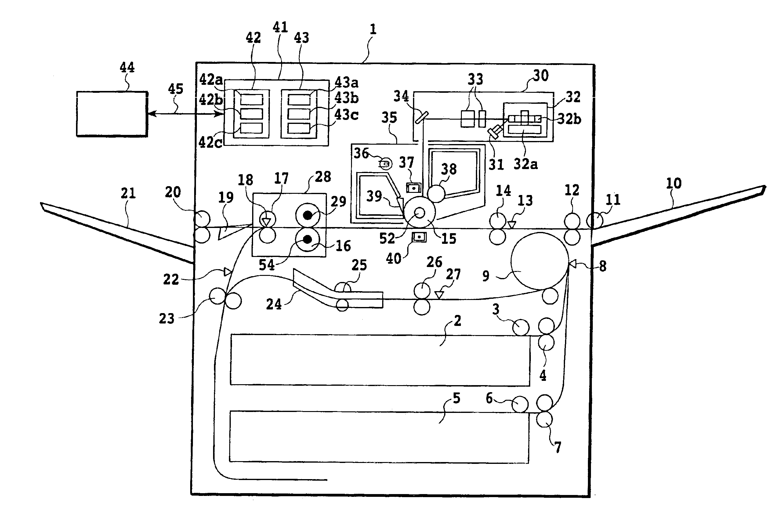
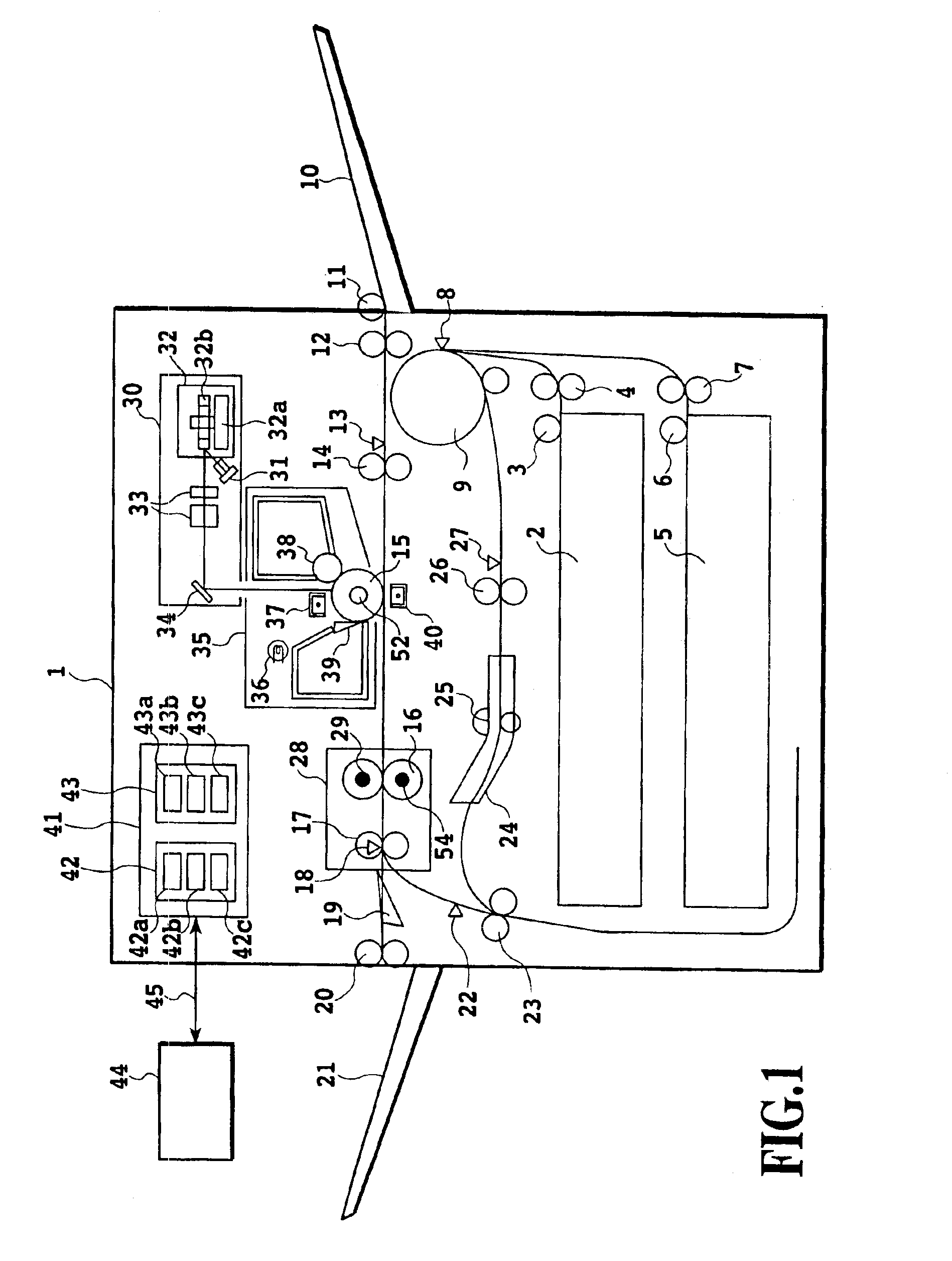
[0056]FIG. 1 is a front view showing an arrangement of a first embodiment of a printing apparatus in accordance with the present invention by way of example of a laser printer. Incidentally, the present invention is applicable to an image formation apparatus using an intermediate or color image formation apparatus. The present invention is also applicable to printing apparatus that form images by the electrophotographic process such as printers besides copiers.

[0057]The main body 1 of the printer includes an upper cassette 2 and a lower cassette 5 for holding recording media. A recording medium is sent out from the upper cassette 2 by an upper pickup feed roller 3, and is conveyed by upper transport rollers 4. In addition, another recording medium is sent out from the lower cassette 5 by a lower pickup feed roller 6, and is conveyed by lower transport rollers 7. The recording medium sent out from the upper cassette 2 or lower cassette 5 is detected by a downstream feed...

second embodiment

[0112]FIG. 11 is a front view showing an arrangement of a second embodiment of the printing apparatus in accordance with the present invention. The second embodiment differs from the first embodiment in the construction of the fixing assembly 28, and hence the description of the same portions as those of the first embodiment will be omitted here. The fixing assembly 28 is a film heating type fixing device, which comprises a heating-pressurizing roller assembly 16 including a heating film and pressurizing roller and a heater 29 consisting of a ceramic heater installed within the heating film.

[0113]A temperature detector not shown is put into contact with the surface of the ceramic heater to control the surface temperature of the heating film at constant by turning on and off the heater in response to the detected result of the temperature. As for the film heating type fixing device, since it is the same as that disclosed in Japanese Patent Application Laid-open No. 9-146391 (1997), t...

third embodiment

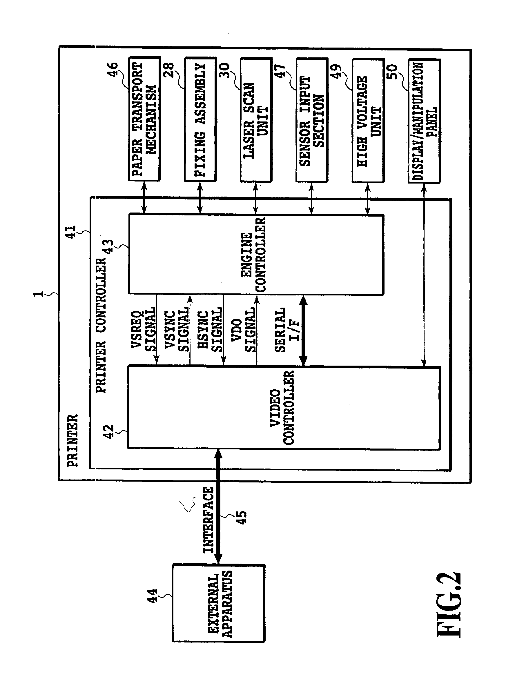
[0121]Since a view showing an arrangement of the third embodiment of the printing apparatus in accordance with the present invention is the same as FIG. 1, the description thereof is omitted here. In addition, since a functional block diagram showing a configuration of the image recording unit associated with the first embodiment in accordance with the present invention is the same as FIG. 2, the description thereof is omitted here. The third embodiment differs from the first embodiment in that in the paper transport mechanism 46, the photoconductive drum and the fixing pressurizing rollers are driven by independent driving sources to make them rotatable individually of each other without interference. Incidentally, although the photoconductive drum driving motor 52 and heating-pressurizing roller driving motor 54 are shown in FIG. 1 as the independent driving sources, one of the photoconductive drum and fixing pressurizing rollers can be driven by using a single motor and clutches....


PUM


Abstract

A printing apparatus can reduce wasted power consumption, and prolong the life of an image forming section and fixing pressurizing rollers. It includes a printer control unit including a video controller and engine controller. According to a print reservation from the video controller, the engine controller controls a paper transport mechanism such as feed rollers, transport rollers and lifters, thereby feeding paper from a paper inlet designated by a printing condition. The engine controller controls a laser scanner unit to transfer a formed image to a sheet with a high voltage unit, and fixes it by a fixing assembly. It controls the paper transport mechanism to output the paper to the paper outlet designated by the printing condition. The image forming section and fixing pressurizing rollers are individually rotatable. Their rotation is stoppable individually without interference in a time from printing the first side to reversing and refeeding the paper.

Description

[0001]This application claims priority from Japanese Patent Application No. 2002-224205 filed Jul. 31, 2002, which is incorporated hereinto by reference.BACKGROUND OF THE INVENTION[0002]1. Field of the Invention[0003]The present invention relates to a printing apparatus, and more particularly to a printing apparatus for forming images by an electrophotographic process such as a copier or printer.[0004]2. Description of the Related Art[0005]A printing apparatus that makes prints on both sides of a recording medium has been commercialized conventionally from a resource / environmental protection viewpoint. The double-sided printing is implemented using a paper reverse mechanism for inverting a paper after printing its first side, and a paper refeed mechanism for feeding the paper again.[0006]In such a type of printing apparatus, a contrivance is made to effectively carry out double-sided printing by determining the number of sheets of paper waiting on the passage of the paper reverse me...

Claims


Application Information

Patent Timeline
Patent Type & Authority Patents(United States)
IPC IPC(8): B65H5/06G03G15/00G03G15/20G03G21/14G03G15/23
CPCG03G15/235G03G15/2064
Inventor ITO, MITSUHIROSAKAI, HIROAKI
Owner CANON KK
Why Eureka
Try Eureka