High power short pulse fiber laser

a fiber laser and short pulse technology, applied in the direction of laser details, active medium materials, active medium shape and construction, etc., can solve the problems of mechanical vibration and environmental instabilities, bulky packaging, and limited practicality of conventional pulse lasers, so as to reduce the width of pulses, and the effect of reducing the optical energy that is coupled from the mode-locked fiber oscillator to the amplifier

Inactive Publication Date: 2005-10-13
IMRA AMERICA
View PDF14 Cites 138 Cited by
  • Summary
  • Abstract
  • Description
  • Claims
  • Application Information

AI Technical Summary

Benefits of technology

[0012] One embodiment of the invention comprises a pulsed fiber laser outputting pulses having a duration and corresponding pulse width. The pulsed laser comprises a modelocked fiber oscillator, an amplifier, a variable attenuator, and a compressor. The a modelocked fiber oscillator outputs optical pulses. The amplifier is optically connected to the modelocked fiber oscillator to receive the optical pulses. The amplifier comprises a gain medium that imparts gain to the optical pulse. The a variable attenuator is disposed between the modelocked fiber oscillator and the amplifier. The variable attenuator has an adjustable transmission such that the optical energy that is coupled from the mode-locked fiber oscillator to the amplifier can be reduced. The compressor compresses the pulse thereby reduces the width of the pulse. Preferably a minimum pulse width is obtained.
[0013] Another embodiment of the invention comprises a method of producing compressed high power short laser pulses having an optical power of at least about 200 mW and a pulse duration of about 200 femtoseconds or less. In this method, longitudinal modes of a laser cavity are substantially mode-locked to repetitively produce a laser pulse. The laser pulse is amplified. The laser pulse is also chirped thereby changing the optical frequency of the optical pulse over time. The laser pulse is also compressed by propagating different optical frequency components of the laser pulse differently to produce compressed laser pulses having a shortened temporal duration. In addition, the laser pulse is selectively attenuated prior to the amplifying of the laser pulse to further shorten the duration of the compressed laser pulses.
[0014] Another embodiment of the invention comprises a method of manufacturing a high power short pulse fiber laser. This method comprises mode-locking a fiber-based oscillator that outputs optical pulses. This method further comprises optically coupling an amplifier to the fiber-based oscillator through a variable attenuator so as to feed the optical pulses from the fiber-based oscillator through the variable attenuator and to the amplifier. The variable attenuator is adjusted based on a measurement of the optical pulses to reduce the intensity of the optical pulses delivered to the amplifier and to shorten the pulse.
[0015] Another embodiment of the invention comprises a pulsed fiber laser outputting pulses having a pulse width. The pulsed fiber laser comprises a modelocked fiber oscillator, an amplifier, and a spectral filter. The modelocked fiber oscillator produces an optical output comprising a plurality of optical pulses having a pulse width and a spectral power distribution having a bandwidth. The amplifier is optically connected to the modelocked fiber amplifier for amplifying the optical pulses. The spectral filter is disposed to receive the optical output of the modelocked fiber oscillator prior to reaching the amplifier. The spectral filter has a spectral transmission with a band edge that overlaps the spectral power distribution of the optical output of the modelocked fiber oscillator to attenuate a portion of the spectral power distribution and thereby reduce the spectral bandwidth. The pulse width of the optical pulses coupled from the mode lock fiber oscillator to the fiber amplifier is thereby reduced.
[0016] Another embodiment of the invention comprises a method of producing compressed optical pulses. In this method, longitudinal modes of a fiber resonant cavity are substantially mode-locked so as to produce a train of optical pulses having a corresponding spectral power distribution with a spectral bandwidth. The optical pulses are amplified and compressed to produce compressed optical pulses. The spectral bandwidth of the spectral power distribution is reduced such that the compressed optical pulses have a shorter duration.
[0017] Another embodiment of the invention comprises a pulsed fiber laser comprising a modelocked fiber oscillator, an amplifier, one or more optical pump sources, a pulse compressor, and a pre-compressor. The modelocked fiber oscillator comprises a gain fiber and a pair of reflective optical elements disposed with respect to the gain fiber to form a resonant cavity. The modelocked fiber oscillator produces a train of optical pulses having an average pulse width. The amplifier is optically connected to the modelocked fiber amplifier such that the optical pulses can propagate through the amplifier. The fiber amplifier amplifies the optical pulses. The one or more optical pump sources are optically connected to the modelocked fiber oscillator and the fiber amplifier to pump the fiber oscillator and fiber amplifier. The pulse compressor is optically coupled to receive the amplified optical pulses output from fiber amplifier. The pulse compressor shortens the pulse width of the optical pulses output by the fiber amplifier. The pre-compressor is disposed in an optical path between the modelocked fiber oscillator and the fiber amplifier. The pre-compressor shortens the duration of the optical pulses introduced into the fiber amplifier such that the pulse duration of the optical pulses output by the compressor can be further shortened.

Problems solved by technology

Currently, conventional pulse lasers have practical limitations.
Such mounting of components can result in a bulky packaging and can suffer from mechanical vibrations and environmental instabilities.

Method used


Image

  • High power short pulse fiber laser
  • High power short pulse fiber laser
  • High power short pulse fiber laser

Examples


Embodiment Construction

[0037] These and other aspects, advantages, and novel features of the present teachings will become apparent from the following detailed description and with reference to the accompanying drawings. In the drawings, similar elements have similar reference numerals.

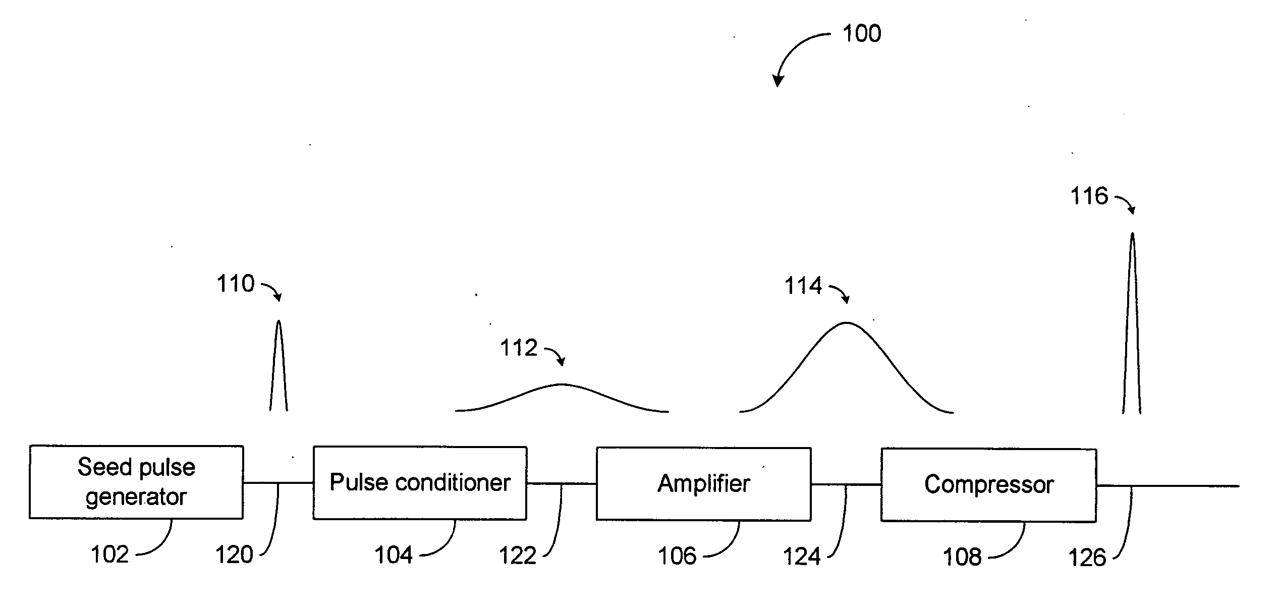
[0038]FIG. 1 illustrates an overall concept of a pulse laser system 100 that outputs a high power short pulse 116. Preferably, the output pulse 116 has a temporal width that is less than approximately 200 femtoseconds (fs), and an average power that is greater than approximately 200 milliwatts (mW). It will be noted that these exemplary performance parameters are in no way intended to limit the scope of the present teachings.

[0039] To achieve a clean short pulse, several techniques can be included such as for example inclusion of attenuators, spectral filters, and compression elements as discussed more fully below. Use of one or more of such components can provide pulse widths of about 90 fs or less and average power of 2...


PUM


Abstract

A pulsed laser comprises an oscillator and amplifier. An attenuator and / or pre-compressor may be disposed between the oscillator and amplifier to improve performance and possibly the quality of pulses output from the laser. Such pre-compression may be implemented with spectral filters and / or dispersive elements between the oscillator and amplifier. The pulsed laser may have a modular design comprising modular devices that may have Telcordia-graded quality and reliability. Fiber pigtails extending from the device modules can be spliced together to form laser system. In one embodiment, a laser system operating at approximately 1050 nm comprises an oscillator having a spectral bandwidth of approximately 19 nm. This oscillator signal can be manipulated to generate a pulse having a width below approximately 90 fs.

Description

BACKGROUND [0001] 1. Field [0002] The present teachings relate to waveguide-based lasers, such as fiber lasers, that output high power short laser pulses. More particularly, the present teachings relate to pulsed lasers that provide improved performance such as reduced pulse width and that preferably include modular designs that are compact and rugged. [0003] 2. Description of the Related Art [0004] High power laser sources are of interest for practical applications in various fields. High peak power pulsed lasers are desirable, for instance, in medical and industrial applications, remote sensing applications, and in optical parametric oscillators. Some specific exemplary applications include use as pump sources for optical amplifiers and Raman lasers for use in medicine and spectroscopy. Rare-earth-doped double clad fiber lasers offer an excellent combination of high power and special beam quality that may be particularly useful. [0005] Various of the following references discuss l...

Claims


Application Information

Patent Timeline
Patent Type & Authority Applications(United States)
IPC IPC(8): H01S3/00H01S3/067H01S3/094H01S3/0941H01S3/098H01S3/102H01S3/13H01S3/16H01S3/23H01S3/30
CPCH01S3/0057H01S3/0064H01S3/0078H01S3/06712H01S3/06741H01S3/1618H01S3/094003H01S3/0941H01S3/1028H01S3/1115H01S3/1305H01S3/06754H01S3/094042H01S3/1698
Inventor GU, XINHUABENDETT, MARKCHO, GYU CHOEN
Owner IMRA AMERICA
Why Eureka
Try Eureka