Apparatus and method for detecting the displacement

Inactive Publication Date: 2002-01-17
TOKYO KEISO
View PDF0 Cites 48 Cited by
  • Summary
  • Abstract
  • Description
  • Claims
  • Application Information

AI Technical Summary

Problems solved by technology

This will increase the measuring error, so that the correct detection on the p

Method used


Image

  • Apparatus and method for detecting the displacement
  • Apparatus and method for detecting the displacement
  • Apparatus and method for detecting the displacement

Examples


Embodiment Construction

[0035] An apparatus and a method for detecting the displacement in accordance with the present invention will now be described with reference to the attached drawings.

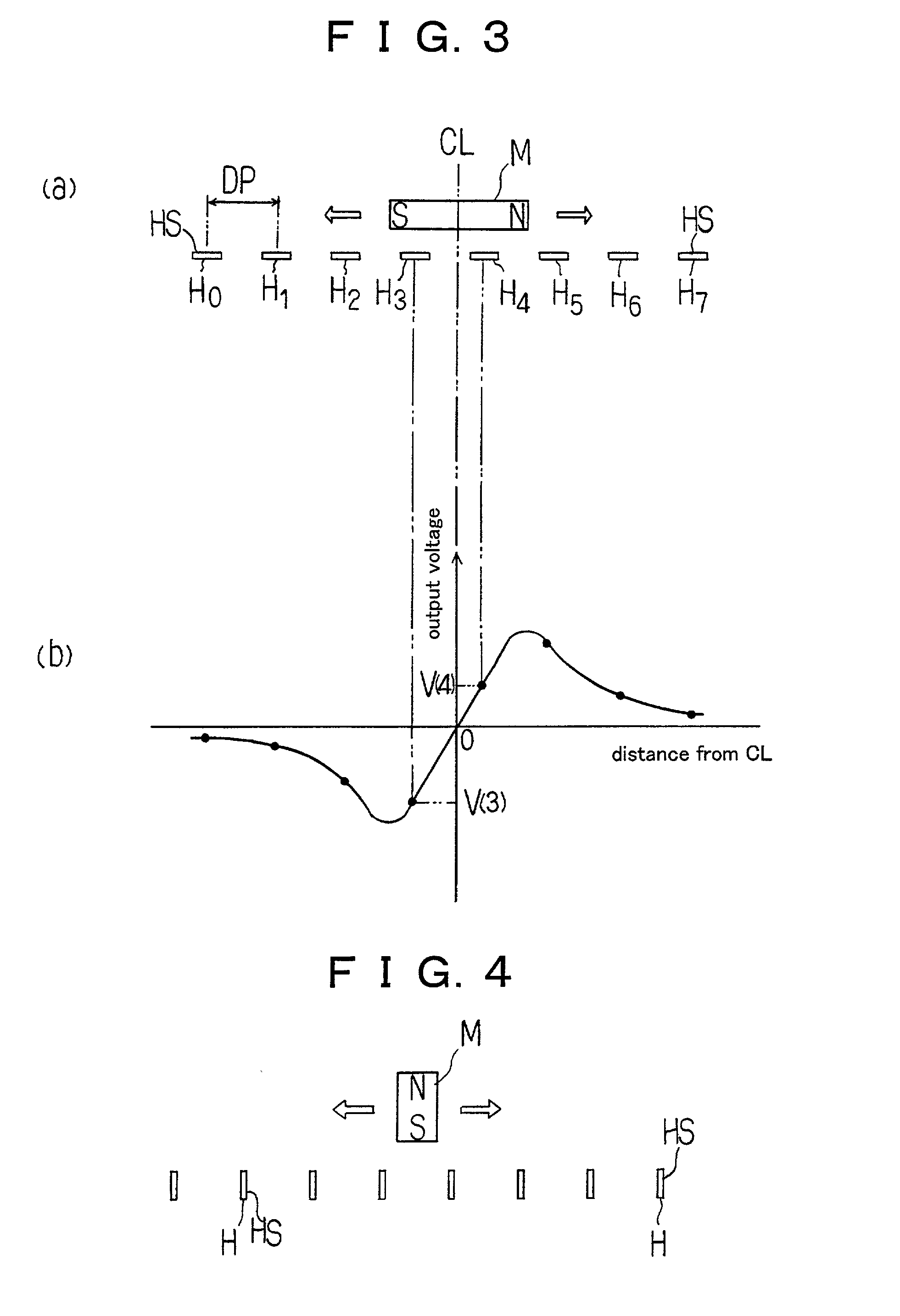
[0036] At first, the basic principle of the apparatus and the method for detecting the displacement in accordance with the present invention will be described with reference to FIGS. 1-3.

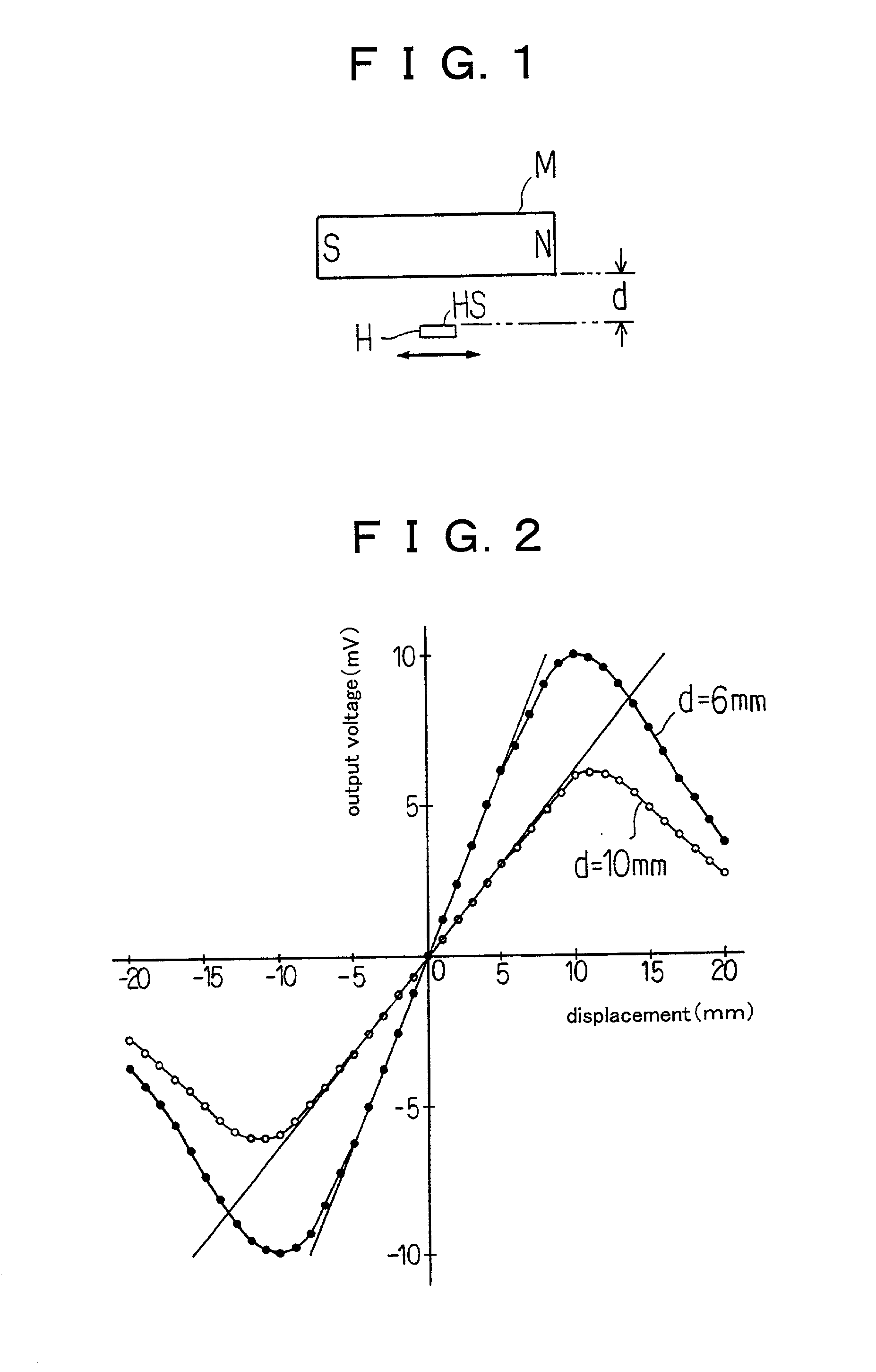
[0037] As shown in FIG. 1, a hall device HS is disposed relative to a magnet M so that a magnetically sensitive surface thereof is in parallel relation with the direction defined by magnetic poles of the magnet. Upon displacing the hall device in parallel with the direction of magnetic flux (in the direction from the left to right in FIG. 1), the output voltage will be generated in the hall device and varied as shown in the graph of FIG. 2.

[0038] The measured results as shown in the graph of FIG. 2 are obtained under the condition that the magnet used is the cylindrical samarium-cobalt magnet of the diameter of 10 mm and the length of ...


PUM


Abstract

An apparatus for detecting the displacement of a magnet is to be provided. The errors on the detected value due to the variation of temperature or that with time are hardly caused in the apparatus. The apparatus can detect the displacement in high resolution and precision. The apparatus is simple in its structure, and it can be expected that the apparatus can be manufactured in low cost. The apparatus is not limited in its application by the range of the displacement of the magnet. Further, a method for detecting the displacement of a magnet will be provided. An apparatus for detecting the displacement of a magnet M, the apparatus being characterized in that it further comprises a plurality of hall devices H0-H7 disposed in a predetermined spacing DP along a displacing path of the magnet in parallel thereto, wherein each of said hall devices includes a magnetically sensitive surface HS through which a magnetic flux from said magnet M permeate to generate an output the polarity and the voltage of which are depend on the direction and the density of the magnetic flux, and said magnetically sensitive surface HS of each hall device is disposed in a predetermined distance from the displacing path of the magnet M in parallel with the direction defined by the magnetic poles, and wherein two adjacent hall devices inverted in the polarity of their output voltages are detected to determine the general position of the magnet, and the precise position of the magnet between these two hall devices is determined on the basis of the output voltages.

Description

[0001] 1. Technical Field[0002] The present invention relates to an apparatus and a method for electrically detecting the displacement of a magnet moved in response to the variation of the physical quantity of measuring instruments such as flowmeters or level gauges, more particularly to a displacement detecting apparatus transforming the displacement of the magnet through hall devices into corresponding electrical signal.[0003] 2. Description of the Prior Art[0004] In the art of the industrial flowmeters or level gauges, used broadly are the displacement detecting apparatus including a magnet adapted to be displaced within a sealed chamber in response to the variation of the measured physical quantity (e.g. the flow rate or the height of the liquid). The measurement of such displacement of the magnet is effected in the exterior of the chamber. The one of such detecting apparatus detects the magnetic lines of flux from the moving magnet.[0005] One example of an area flowmeter includ...

Claims


Application Information

Patent Timeline
IPC IPC(8): G01B7/00G01B7/30G01D5/14G01F1/22G01F1/24G01F23/62
CPCG01B7/003G01D5/145G01F1/24G01F23/62G01F23/0038
Inventor SATO, KENJI
Owner TOKYO KEISO
Why Eureka
Try Eureka