Connector for flexible pipes having at least one resilient sealing ring

a flexible pipe and resilient sealing technology, applied in the direction of hose connection, pipe connection arrangement, pipe/joint/fitting, etc., can solve the problems of poor flexibility characteristics, poor ability, and insatiable seal between the pipe and the coupling element to prevent the escape or leakage of operating fluid

Inactive Publication Date: 2002-02-28
MANULI AUTO ITALA
View PDF0 Cites 33 Cited by
  • Summary
  • Abstract
  • Description
  • Claims
  • Application Information

AI Technical Summary

Problems solved by technology

A disadvantage of known connectors is that the characteristics of the seal between the pipe and the coupling element for preventing the escape or leakage of the operating fluid are not entirely satisfactory when the fluid has small molecular dimensions.
This problem is accentuated by the fact that, in order to reduce the permeability of the pipes to fluids of this type, flexible pipes having an internal sheathing of polyamide material, particularly nylon, are often used.
As is known, polyamide materials generally have poor flexibility characteristics and hence a poor ability to adapt to the gripping teeth of the coupling elements of the connectors, particularly to ramp-like annular teeth, with the risk of imperfect adhesion between the inside wall of the pipe and the coupling element, although only in a localized region.
Another disadvantage of known connectors connected to flexible pipes having an internal polyamide sheathing is caused by the difference between the coefficient of thermal expansion of the sheathing and that of the metal of which the connector, including any sealing collars, is made.
This difference between the coefficients of thermal expansion means that the coupling element of the connector tends to contract radially to a greater extent or more rapidly than the flexible pipe as a result of abrupt reductions in the running temperature, with the consequent danger of the fluid leaking.

Method used


Image

  • Connector for flexible pipes having at least one resilient sealing ring
  • Connector for flexible pipes having at least one resilient sealing ring

Examples


Embodiment Construction

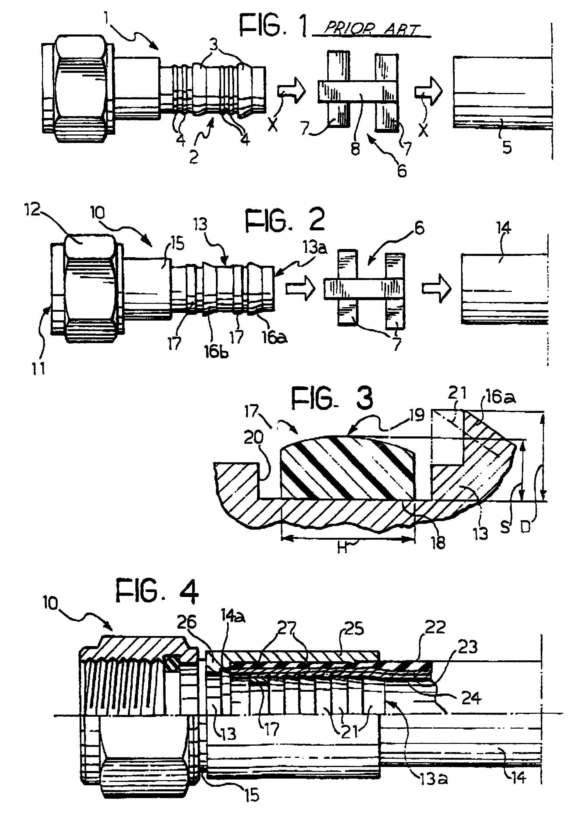
[0022] With reference now to the drawings, FIG. 1 shows a known connector, the characteristics of which have already been described above in the introduction to the present description. In this drawing, the direction in which the components (the connector, the clamping collar and the flexible pipe) are assembled when the connector is in use is shown by the arrows X.

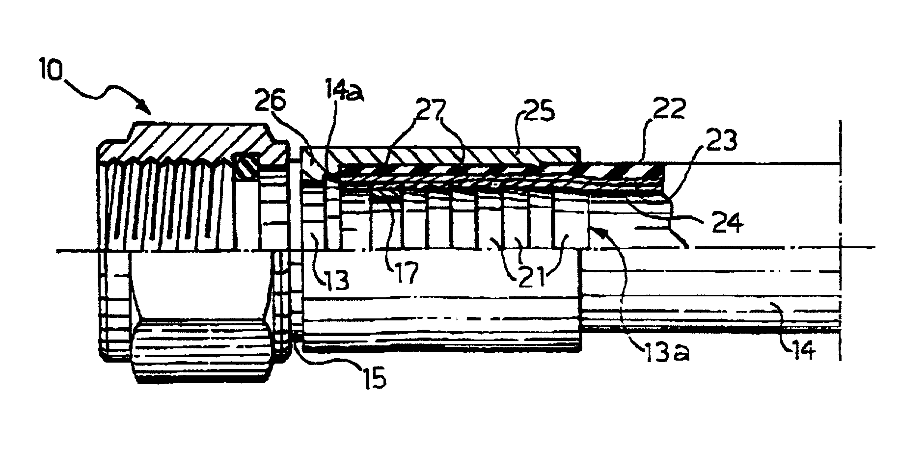
[0023] FIG. 2 shows a connector according to the present invention, comprising an elongate, hollow body, generally indicated 10, having an internally threaded opening at its end which is on the left in the drawing. A nut 12 is formed integrally on the connector 10 to enable the opening 11 to be screwed onto a corresponding rigid threaded member of the system in which the connector is used. At the opposite end to the opening 11, the connector 10 has a tubular coupling element 13 for the fitting of a flexible pipe 14 of known type.

[0024] An intermediate tubular portion 15 having an outside diameter larger than the outside d...


PUM

PropertyMeasurementUnit
resilient behaviouraaaaaaaaaa
flexibleaaaaaaaaaa
widthaaaaaaaaaa

Abstract

A connector (10) for flexible pipes, particularly for use in cooling or air-conditioning systems for motor vehicles, comprises a hollow main body including a coupling element (13) for a flexible pipe, the coupling element having at least one gripping tooth (16a, 16b) for cooperating with clamping means (6) to grip a flexible pipe (14) when the connector is in the condition of use. The connector comprises at least one sealing ring (17) having a substantially cylindrical inside wall (18) and a shaped, preferably arcuate, outside wall (19). The sealing ring (17) exhibits resilient behavior in a radial direction and is compressed radially, when the connector (10) is in the condition of use, by the flexible pipe (14) which is fitted and clamped on the coupling element (13) by the clamping means (6).

Description

[0001] 1. Field of the Invention[0002] The present invention relates to a connector for flexible pipes, particularly for use in cooling or air-conditioning systems for motor vehicles, of the type comprising a hollow main body including a coupling element for a flexible pipe, the coupling element having at least one gripping tooth for cooperating with clamping means to grip the flexible pipe when the connector is in the condition of use.[0003] 2. Description of the Related Art[0004] An example of a connector of the known type indicated above is illustrated and generally indicated 1 in the appended FIG. 1. This connector has a tubular coupling element 2 on which two ramp-like, annular teeth 3 and two pairs of sealing collars 4 are formed integrally. In use, the end of a flexible pipe 5 is fitted and clamped on the coupling element 2 by the plastic deformation of a collar 6 which, in the example of FIG. 1, is constituted by a pair of bands 7 connected in a tandem configuration by a tra...

Claims


Application Information

Patent Timeline
Patent Type & Authority Applications(United States)
IPC IPC(8): F16L33/207
CPCF16L33/02F16L33/2076
Inventor MANULI, DARDANIO
Owner MANULI AUTO ITALA
Why Eureka
Try Eureka