Surface light source device and liquid crystal display

a light source device and liquid crystal display technology, applied in the direction of identification means, lighting and heating apparatus, instruments, etc., can solve the problems of excessive directivity of output light, sharp reduction in brightness, narrow viewing angle, etc., to improve angular extent, excellent angular extent and isotropy of viewing field

Inactive Publication Date: 2003-08-21
ENPLAS CORP
View PDF3 Cites 5 Cited by
  • Summary
  • Abstract
  • Description
  • Claims
  • Application Information

AI Technical Summary

Benefits of technology

0059] An object of the present invention is to solve the above-mentioned problem and to provide a surface light source device that has an improved angular extent and isotropy around an ou

Problems solved by technology

However, in prior arts employing micro-reflectors in the standard posture tends to cause the output light to have an excessive directivity, being suffered from a problem that a small deviation of viewing direction from a main emission direction (i.e. direction of Q1 and Q2) brings a sharp reduction in brightness (Narrow viewing angle).
In particular, a posture on z-axis is made fitting in with the above-mentioned Condition 1, there rises a drawback that viewing angle in zx-pane differs much from that in yz-pane and the latter (viewing angle in yz-pane) is very small.
This means that only a small angular deviation of viewing from the peak direction (i.e. brightest viewing direction) regarding .+-.y-directions brings a sharp reduction in brig

Method used


Image

  • Surface light source device and liquid crystal display
  • Surface light source device and liquid crystal display
  • Surface light source device and liquid crystal display

Examples


Embodiment Construction

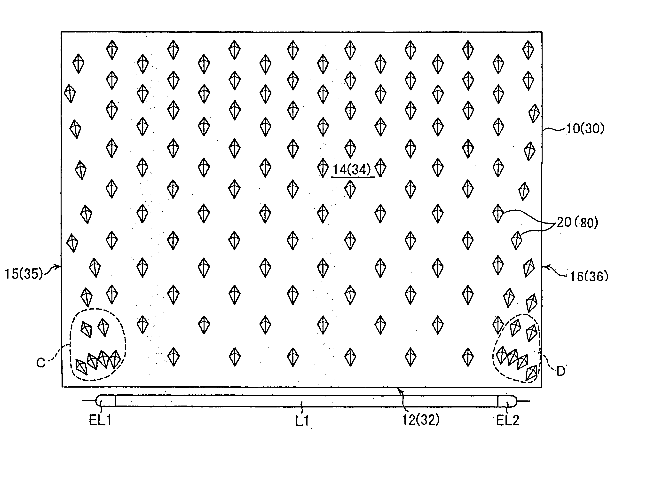
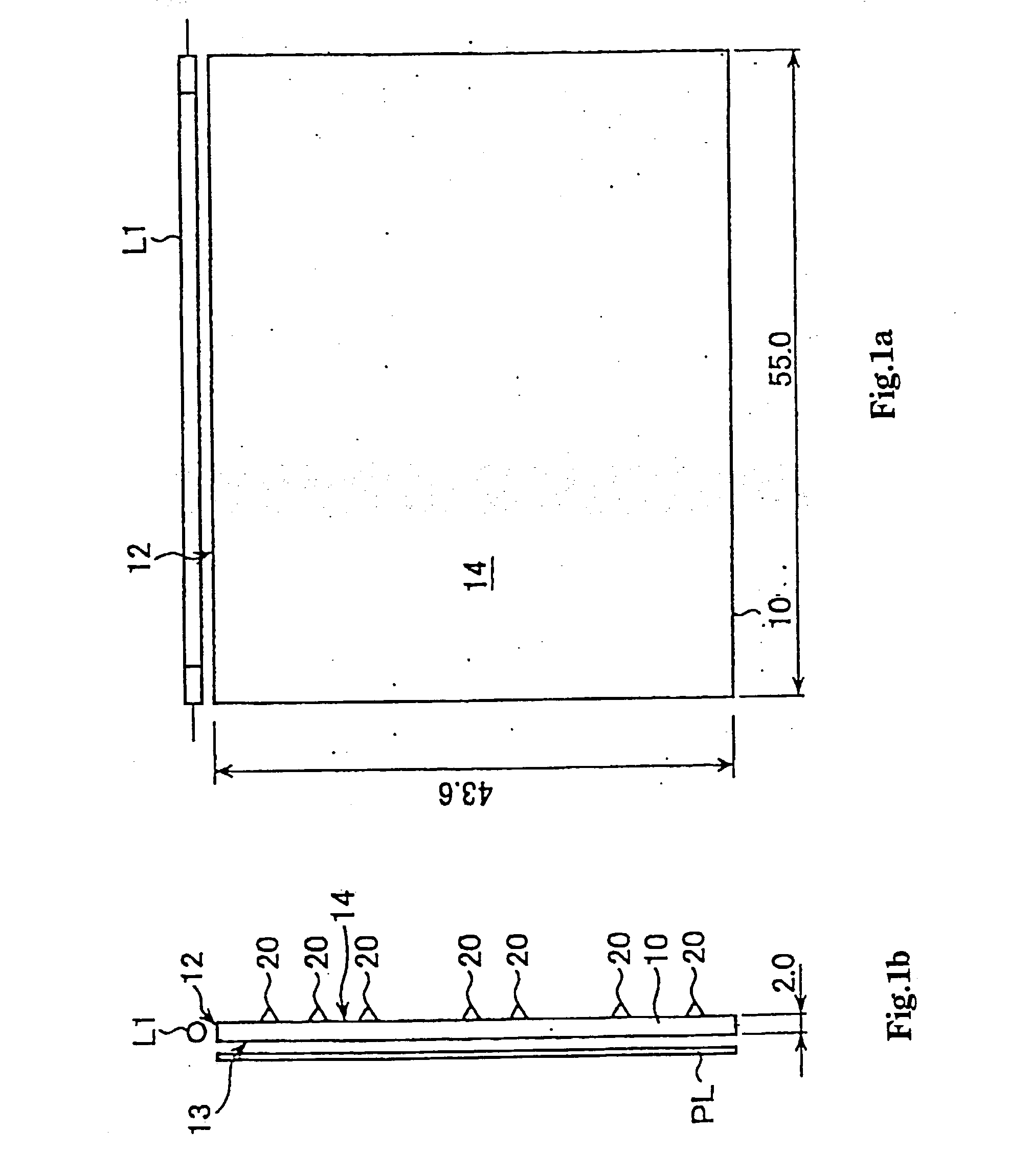
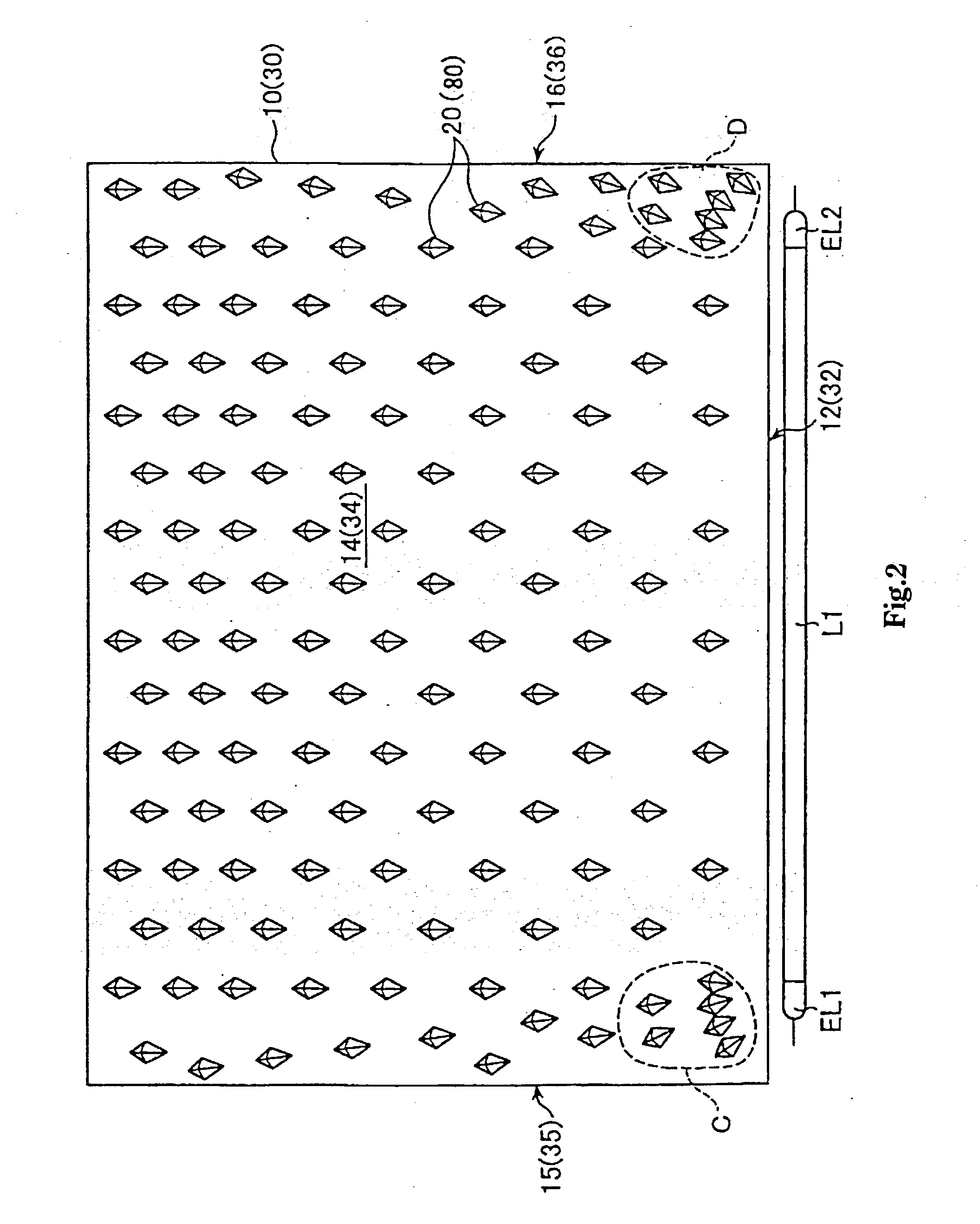
[0093] Description on a liquid crystal display of an embodiment in accordance with the present invention is provided hereafter. In the first place, an outlined arrangement is shown in FIGS. 9a and 9b is the same manner as FIGS. 1a and 1b, FIG. 9a being a plan view from a back face side of a light guide plate, and FIG. 9b being a side view from the left side in FIG. 9a.

[0094] Although basic arrangement relation among a primary light source, light guide plate and liquid crystal display panel is the same as that shown in FIGS. 1a and 1b as shown in FIGS. 9a and 9b, a guide plate 30 provided with a feature of the present invention is employed instead of the light guide plate 30 and a light diffusion sheet DF is interposed between the light guide plate 30 and liquid crystal display panel PL.

[0095] The light guide plate 30 is made of a transparent material such as acrylic resin, polycarbonate (PC) or cycloolefin-type resin, like the light guide plate 10. A side end face of the light guide...


PUM


Abstract

Provided are surface light source devices and LCDs having isotropic and wide viewing angles. A surface light source device for illuminating an LCD comprises a light guide plate hiving a back face provided with a great number of micro-reflectors. Light beams P1, P2 representing an inner input light are inner-reflected by first and then second inner reflection faces or in inverse order, respectively to become a first and second inner output lights Q1 and Q2 which are non-parallel to each other, providing an emission having angular intensity characteristics showing two peaks. Peak splitting of the emission is dissolved by a light diffusion sheet disposed along an emission face of the light guide plate, causing an LCD panel to be illuminated by an isotropic and wide-view-angled illumination output light. The first and second inner reflection faces may be inclined oppositely and symmetrically to each other with respect to an imaginary reference plane that passes a valley bottom of a micro-reflector and extends perpendicularly to the emission face.

Description

[0001] 1. Field of Invention[0002] The present invention relates to a surface light source device and liquid crystal display, in particular, to a surface light source device utilizing a light guide plate having a back face provided with a great number of micro-reflectors and a liquid crystal display utilizing the surface light source device for illuminating a liquid crystal display panel.[0003] The present invention is applied, for example, to liquid crystal displays in devices such as personal computers, car navigation systems or portable phones and surface light source devices used therein.[0004] 2. Related Art[0005] A well-known surface light source device uses a light guide plate that has an end portion and an emission face, wherein light is supplied and introduced into the light guide plate through the end portion and is outputted through the emission-face, being applied to broad uses such as illumination of liquid crystal display panels.[0006] Although rod-like fluorescent lam...

Claims


Application Information

Patent Timeline
IPC IPC(8): F21V8/00G02F1/1335F21Y103/00G02F1/13357G09F9/00G09F9/35
CPCG02B6/0028G02B6/0068G02B6/0061G02B6/0036G02F1/1335
Inventor OHKAWA, SHINGO
Owner ENPLAS CORP
Why Eureka
Try Eureka