

Cooling the upstream end plate of a high pressure turbine by means of a system of dual injectors at the end of the combustion chamber
a technology of high-pressure turbines and injectors, which is applied in the direction of turbines, piston pumps, marine propulsion, etc., can solve the problems of reducing the performance of the turbine, increasing the flow rate, and increasing the temperature of the upstream face of the end plate downstream from the second baffle, so as to and improve the efficiency of the turbine. , the effect of improving the li
- Summary
- Abstract
- Description
- Claims
- Application Information
AI Technical Summary
Benefits of technology
Problems solved by technology
Method used
Image

Examples
Embodiment Construction
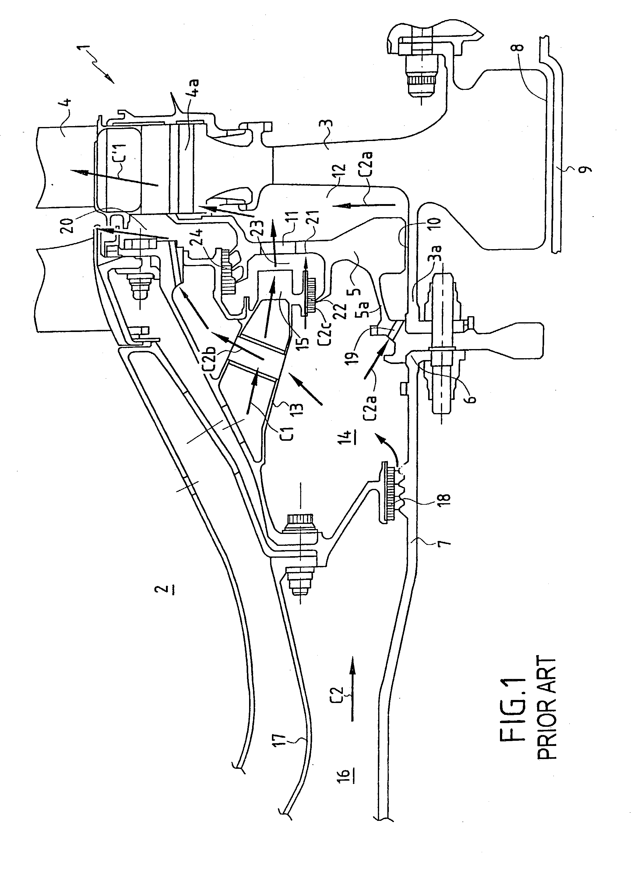
[0021] The state of the art shown in FIG. 1 is described in the introduction and needs no further explanation.
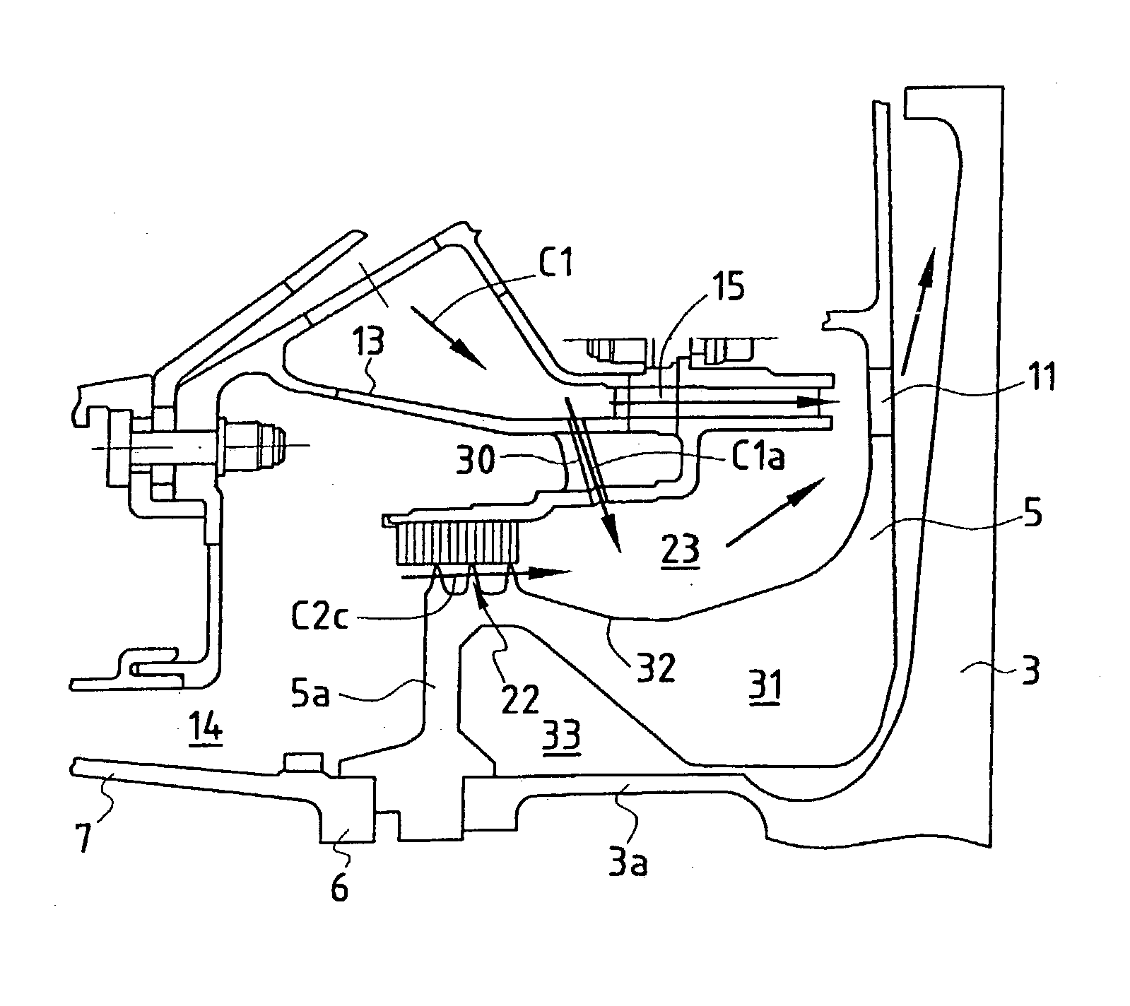
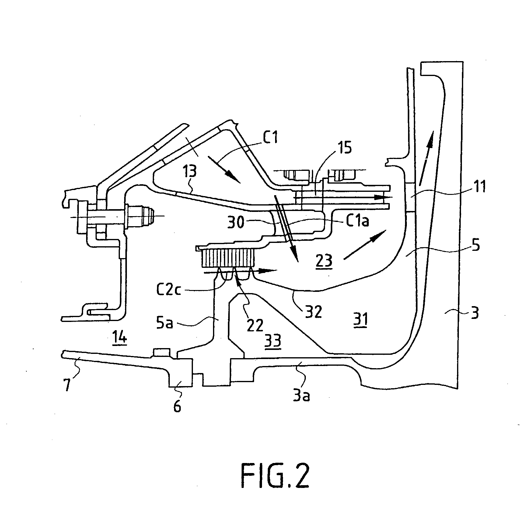
[0022] FIG. 2 shows a turbine rotor 1 which differs from that shown in FIG. 1 by the fact that the enclosure 23 situated downstream from the second baffle 22 is fed with air firstly by an air leak C2c coming from the enclosure 14 via the second baffle 22, and secondly by an air flow C1a delivered by a branch connection formed between the duct 13 delivering the first air flow C1 and the enclosure 23. The branch connection is constituted by a plurality of bores 30 opening out at one end into the inlets of the main injectors 15, and at the other end into the enclosure 23 immediately downstream from the second baffle 22. The bores 30 are cylindrical and inclined tangentially in the direction of rotation of the turbine rotor 1.
[0023] As can be seen in FIG. 2, the radially inner portion 31 of the end plate 5 is bulky in shape, and it extends axially towards the front end of the en...
PUM
 Abstract
Description
Claims
Application Information