Apparatus for positioning and stabbing pipe in a drilling rig derrick

a technology for positioning and stabbing pipes, which is applied in the direction of drilling casings, drilling pipes, borehole/well accessories, etc., can solve the problems of not being useful for stabbing and manipulating large diameter casings, the threads of drilling pipes are relatively difficult to misalign, and the rig workers' manual positioning of drilling casings within the derricks is difficult, if not impossible, to achieve the effect of preventing a large diameter casing from slipping and falling, and the rig

Inactive Publication Date: 2004-03-11
HOOPER ROBERT C +1
View PDF5 Cites 46 Cited by
  • Summary
  • Abstract
  • Description
  • Claims
  • Application Information

AI Technical Summary

Benefits of technology

0032] A further object of the invention is to provide a pipe stabbing apparatus which can grip and steer tubular goods, including large diameter pipe such as casing, and which allows such pipe to be spun or rotated about its longitudinal axis, even while such pipe is engaged...

Problems solved by technology

Accordingly, drill pipe threads are relatively difficult to misalign when joints of drill pipe are brought into end-to-end abutting relationship for threaded interconnection.
By contrast, because casing is generally much heavier than drill pipe and other similar tubular goods, it is often difficult, if not impossible, for rig workers to manually position such casing within a derrick.
The device is used solely for the racking of drill pipe of relatively small diameter, and would not be useful for stabbing and manipulating large diameter casing.
The device described in Swoboda cannot be used for stabbing casing from an elevated location above the rig floor in the derrick, especially large diameter casing.
The apparatus described in True is not well adapted for engaging and positioning sections of pipe having large diameters such as casing.
Furthe...

Method used


Image

  • Apparatus for positioning and stabbing pipe in a drilling rig derrick
  • Apparatus for positioning and stabbing pipe in a drilling rig derrick
  • Apparatus for positioning and stabbing pipe in a drilling rig derrick

Examples


Embodiment Construction

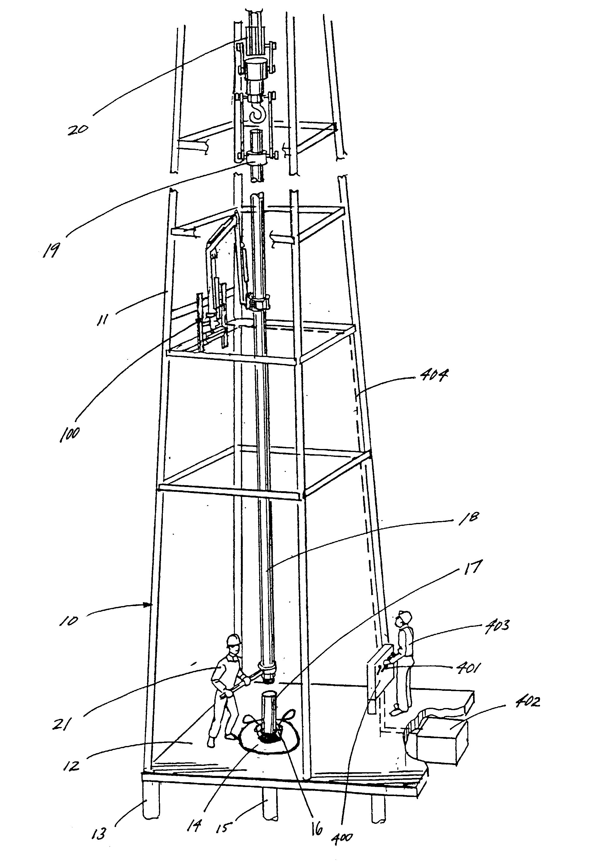
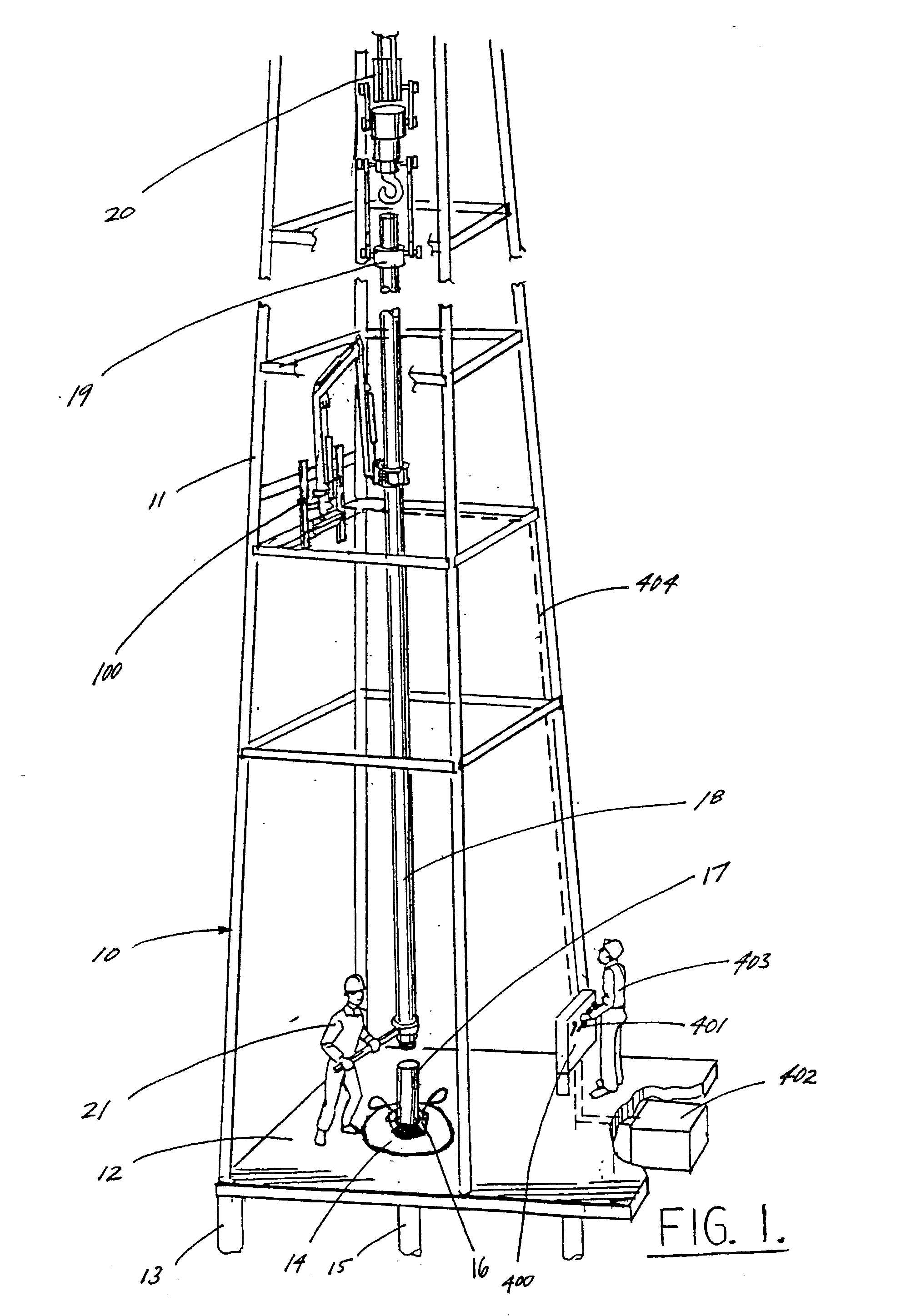
[0042] Referring initially to FIG. 1 of the drawings, drilling rig 10 is depicted during operations for the installation of casing into a well. Vertically extending derrick 11 and rig floor 12 are supported on drilling platform 13. Rotary 14, which is positioned on rig floor 12 at the surface of well 15, supports, by means of suitable lower slips 16, an elongated section of casing 17. The upper portion of casing section 17 protrudes out of rotary 14 and is situated above rig floor 12, while the remainder of casing section 17 projects downwardly from the rig floor and, ultimately, into the well 15 being drilled or serviced.

[0043] When installing casing into well 15, it is necessary to serially interconnect multiple sections of casing at a point of joinder a short distance above rig floor 12. The process is commenced by installing a first section of casing 17 into well 15, and hanging or suspending same in place using lower slips 16. As succeeding sections of casing are added to the c...


PUM


Abstract

A remotely controlled apparatus for positioning and stabbing pipe within a drilling rig derrick is provided. A support base assembly is mounted to a structural member of a drilling rig derrick. A jointed articulating boom having a boom base member and a boom arm member is attached to the support base assembly and can be pivoted about vertical and horizontal axes. The jointed articulating boom extends and retracts by cooperative motion between the boom base member and the boom arm member. A pipe gripper assembly having opposing arcuate jaws is mounted at the outer extent of the jointed articulating boom and can be pivoted about a horizontal axis. A remote control panel subassembly is used to control the movement of jointed articulating boom and pipe gripper assembly.

Description

[0001] 1. Field of the Invention[0002] This invention relates to an apparatus for positioning and stabbing tubular goods, including large diameter pipe such as casing, within a drilling rig derrick. More particularly, the present invention pertains to an apparatus which can be mounted within a drilling rig derrick, and which can grip a section of pipe, such as large diameter casing, suspended within said derrick. More particularly still, the present invention pertains to a remotely operated apparatus which can grip a section of pipe suspended within a drilling rig derrick and align such pipe so that threads at the lower end thereof can be joined with mating threads of a section of pipe situated therebelow.[0003] 2. Brief Description of the Prior Art[0004] Standard rotary drilling rigs are typically comprised of a supportive rig floor, a roughly vertical derrick extending above said rig floor, and a traveling block which can be raised and lowered within said derrick. Such rig equipme...

Claims


Application Information

Patent Timeline
IPC IPC(8): E21B19/20
CPCE21B19/20
Inventor HOOPER, ROBERT C.SPISAK, TIMOTHY M.
Owner HOOPER ROBERT C
Why Eureka
Try Eureka