Electronic apparatus, image forming system, video printing system and camera-incorporated recording/reproducing apparatus

Inactive Publication Date: 2005-02-03
CANON KK
View PDF20 Cites 4 Cited by
  • Summary
  • Abstract
  • Description
  • Claims
  • Application Information

AI Technical Summary

Benefits of technology

[0006] To resolve the above problem, it is one object of the present invention to provide an electronic apparatus that can perform data communication at high speed.
[0007] It is another object of the present invention to improve the usability of an image forming system, a video printing system and a camera-incorporated recording / reproduction apparatus for these systems.
[0008] It is an additional object of the present invention to provide an electronic apparatus, a video printing system and an image forming system with which data communication with an external device can be performed at high speed.

Problems solved by technology

However, since such a video printing system employs analog signals for communication, bidirectional communication with an external device is difficult.

Method used


Image

  • Electronic apparatus, image forming system, video printing system and camera-incorporated recording/reproducing apparatus
  • Electronic apparatus, image forming system, video printing system and camera-incorporated recording/reproducing apparatus
  • Electronic apparatus, image forming system, video printing system and camera-incorporated recording/reproducing apparatus

Examples


first embodiment

[0156] (First Embodiment)

[0157] The preferred embodiments of the present invention will now be described in detail while referring to the accompanying drawings.

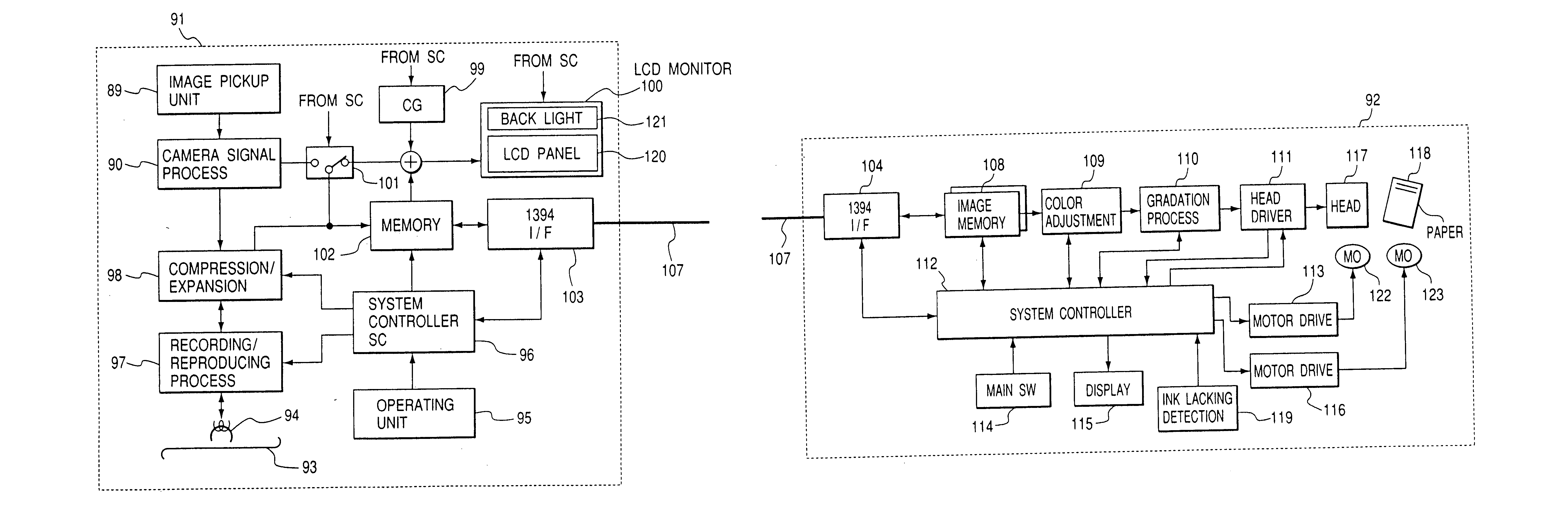
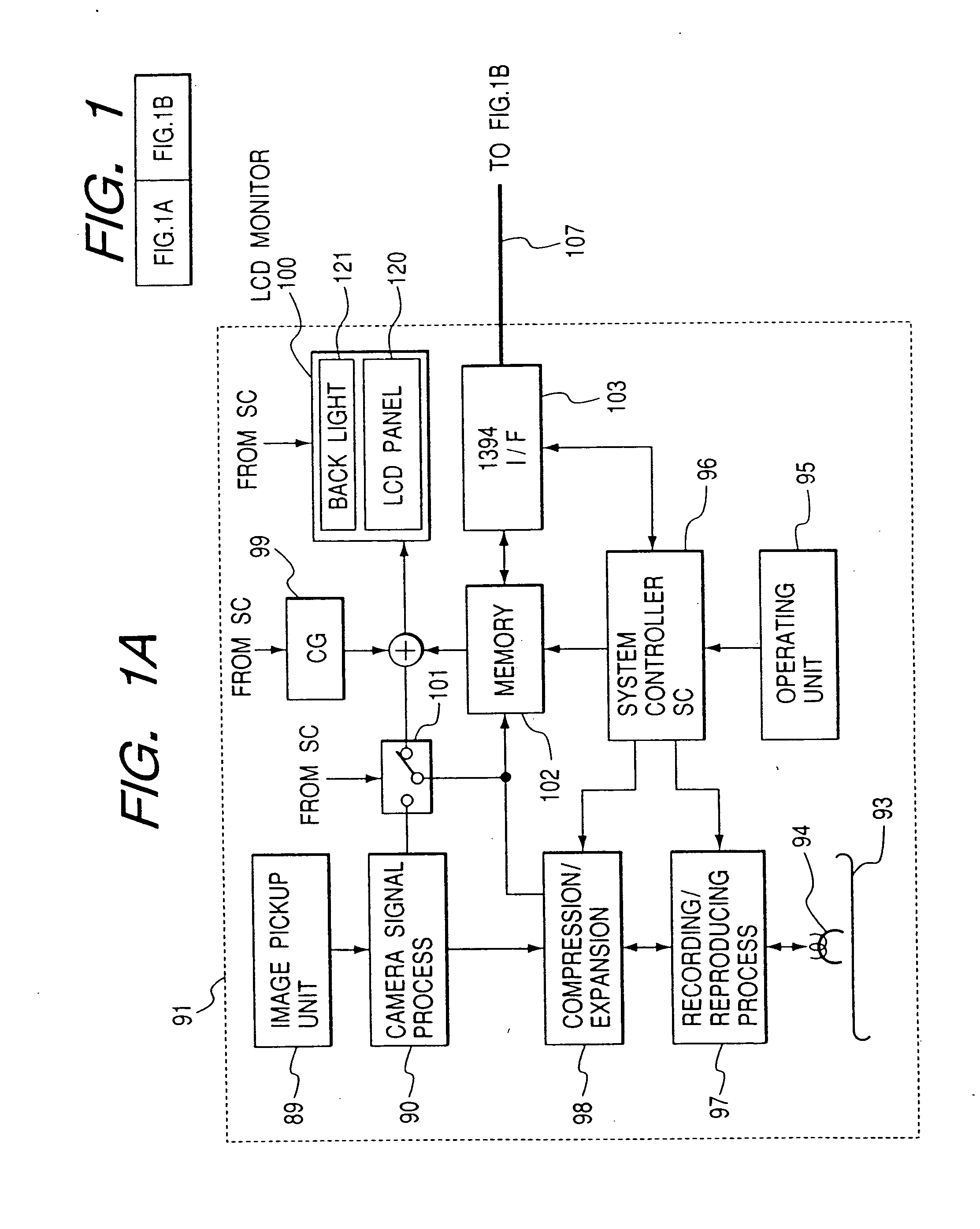
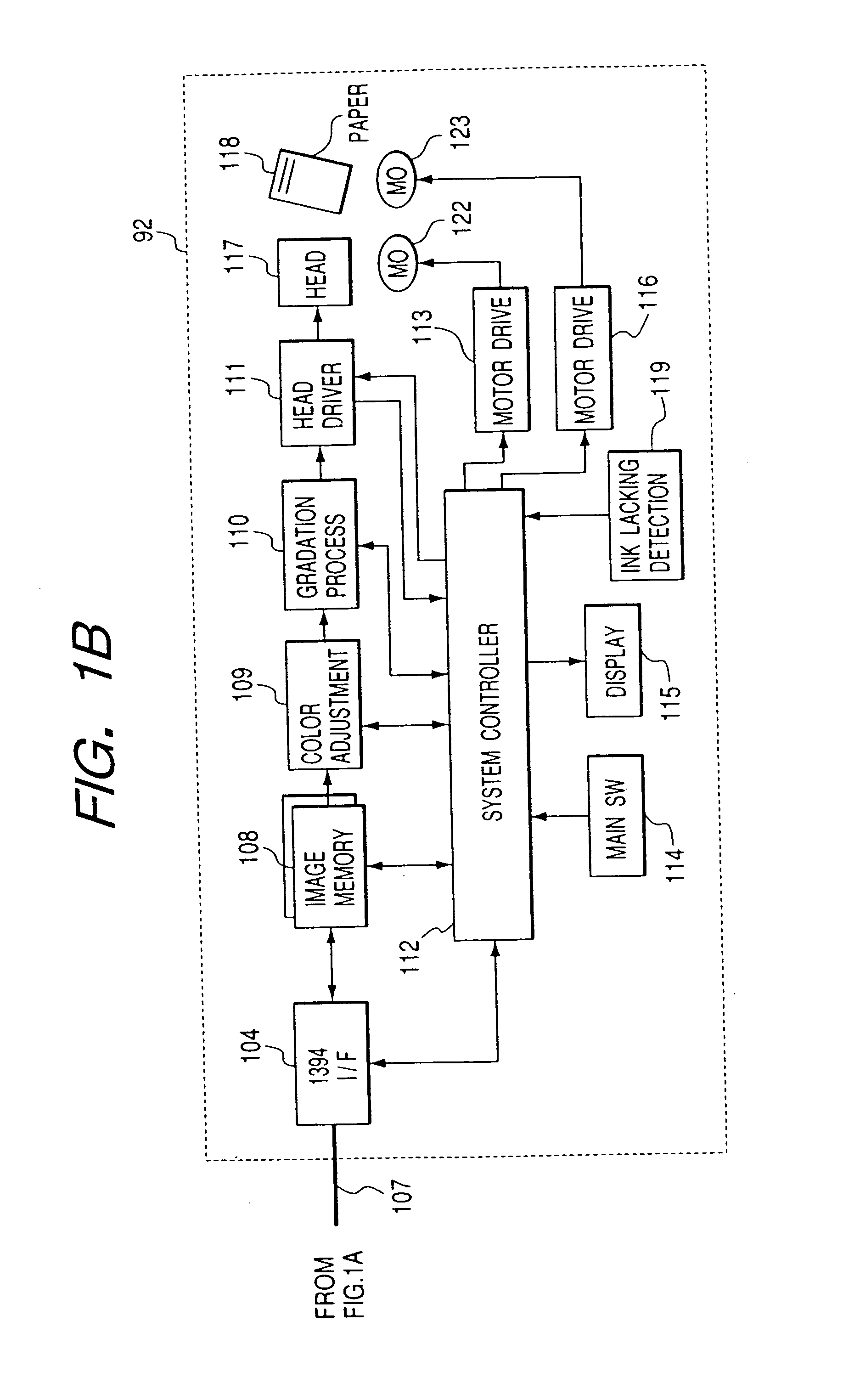
[0158]FIGS. 1A and 1B are block diagrams illustrating an ink-jet printer and a camera-incorporated digital VTR with a liquid crystal monitor, which are connected via an IEEE 1394 serial bus.

[0159] In FIGS. 1A and 1B, a camera-incorporated digital VTR having a liquid crystal monitor (hereinafter referred to as a “digital VTR”) 91 comprises: a magnetic tape 93; a head 94 for recording / reproducing data on the magnetic tape 93; an operating unit 95 for entering operation commands for the digital VTR 91; a system controller 96 for controlling the digital VTR 91 by using a microcomputer; a recording / reproducing processor 97 for recording / reproducing video data that are read by the head 94; a compression / expansion unit 98 for compressing or expanding the video data; a CG (Character Generator) 99 for generating characters, etc., to...

second embodiment

[0207] (Second Embodiment)

[0208] A second embodiment for which a power saving mode is provided will now be described while referring to the flowchart in FIG. 6.

[0209] First, a printing command is executed by the main body of a digital VTR, or by a remote controller (S50), and the transmission of image data from the digital VTR to a printer is begun (S51). The backlight of an LCD monitor provided for the digital VTR is powered off (S52), and as a result, the power saving of the digital VTR can be implemented. This is preferable, especially when for printing the digital VTR is powered by a battery, such as a lithium ion battery.

[0210] Upon the receipt of the data, the printer begins to print. When the ink runs out after a predetermined number of sheets have been printed (S53), the communication of image data is halted (S54). So long as the ink does not run out, the normal printing process continues, and at this time, the backlight is again powered off.

[0211] Upon the occurrence of ...


PUM


Abstract

The object of the present invention is, while employing only a simple structure, to engage in rapid communication with an external device and to display results of the communication. According to the present invention, disclosed is an electronic apparatus, which comprises conversion means for converting a target image into image signals, supply means for supplying, to a monitor, signals in consonance with the image signal obtained by the conversion means in order to reproduce the target image, communication means for using a DS-Link method to perform bidirectional communication with an external device handling the image signal for the target image and control means for displaying on the monitor information concerning the external device that is obtained by the communication means.

Description

BACKGROUND OF THE INVENTION [0001] 1. Field of the Invention [0002] The present invention relates to an image pickup apparatus, an image forming system, and a video printing system. [0003] 2. Related Background Art [0004] In a conventional video printing system, for example, a video printer is connected as an external device to an analog recording camera-incorporated VTR, and a desired static picture is searched for and is output by the video printer. [0005] However, since such a video printing system employs analog signals for communication, bidirectional communication with an external device is difficult. Therefore, because of image quality and printing speed, an image forming system and a printing system that transmit digital moving pictures in real time have been demanded. SUMMARY OF THE INVENTION [0006] To resolve the above problem, it is one object of the present invention to provide an electronic apparatus that can perform data communication at high speed. [0007] It is anothe...

Claims


Application Information

Patent Timeline
IPC IPC(8): G06F3/12H04N5/76
CPCG06F3/121G06F3/1212G06F3/1235Y02B60/1271G06F3/128G06F3/1284G06F3/1259Y02D10/00
Inventor KAWAI, KENJI
Owner CANON KK
Why Eureka
Try Eureka